1. The Real Question: Can the Calculation Finish in Time?
In motor-control applications, the hardest part is not always implementing the algorithm. More often, it is completing the calculation within the available cycle budget.
This is especially true in single-axis servo drives, magnetic encoders, and resolver-based systems, where angle computation must be performed during every control cycle. A typical task is to convert a sine/cosine pair or an (x, y) vector into an angle using atan2, then feed the result into the position, speed, and current control loops.
But what happens when the MCU does not have an FPU?
A software implementation of atan2 can consume a significant number of cycles. Once the control-loop frequency reaches 20 kHz or even 40 kHz, the interrupt service routine can quickly run out of execution time.
The G32R430 takes a different approach. Instead of relying on a general-purpose floating-point datapath, it uses a CDE-enabled hardware TMU to accelerate the ATAN2 operation.
This article focuses on three questions:
- Why is
atan2 essential in encoder applications?
- How does the G32R430 accelerate
ATAN2 through its CDE-based hardware path?
- How much faster is it in actual cycle-count measurements?
—
2. Test Setup
To keep the comparison clear, the benchmark uses the following configuration:
- Device/core: G32R430, based on a customized Arm Cortex-M52 implementation with CDE support and no FPU, DSP, or MVE in the tested configuration
- SDK: G32R430 DDL SDK V1.0.2
- Example path:
Examples/Board_G32R430_Tiny/ATAN2/ATAN2_Math/
- Header file:
Libraries/ATAN2/MathLib.h
- Example source file:
ATAN2_Math/Source/main.c
- Main API:
int32_t ATAN2(int32_t nX, int32_t nY, int32_t nPrecisionLevel);
- Compiler configuration: consistent with the official example project, such as:
-mcpu=cortex-m52+nomve+nofp+cdecp3
- System clock: 120 MHz
- Cycle measurement: DWT cycle counter
—
3. Why ATAN2 Matters
Resolvers and magnetic encoders commonly provide a pair of signals corresponding to sin θ and cos θ. The angle can then be calculated as:
θ = atan2(sin θ, cos θ)
This operation is also frequently used in field-oriented control. Clarke and Park transforms, as well as their inverse transforms, depend on the current electrical angle.
In other words, atan2 is not an optional refinement. It often sits directly in the real-time control path. Its execution speed and timing consistency can directly affect closed-loop performance.
—
4. The G32R430 Approach: Purpose-Built Acceleration
Many MCUs are designed as general-purpose devices with a broad set of computing resources. The G32R430 takes a more application-focused approach:
- It does not rely on an FPU, DSP, or MVE for this calculation
- It introduces a CDE-based hardware acceleration path
- It targets high-frequency fixed-point operations such as electrical-angle computation
The design principle is straightforward: allocate the silicon budget to the operations that encoder and servo applications execute most frequently.
—
5. Using the CDE-Accelerated ATAN2 API
The SDK provides the following interface:
/**
* @brief Computes the angle of a point defined by nX and nY
* in a two-dimensional plane.
*
* @param nX X-axis coordinate in fixed-point format.
* @param nY Y-axis coordinate in fixed-point format.
* @param nPrecisionLevel Precision level from 1 to 8.
* A higher level improves accuracy but
* increases execution time.
* Recommended values: 6, 7, and 8.
*
* @return Normalized angle in Q31 format within (-1, 1],
* corresponding to the angular range (-pi, pi].
*/
int32_t ATAN2(int32_t nX, int32_t nY, int32_t nPrecisionLevel);
The parameters are used as follows:
nX and nY: fixed-point input coordinatesnPrecisionLevel: selectable precision level from 1 to 8; levels 6, 7, and 8 are recommended for typical use- Return value: a normalized Q31 result within
(-1, 1], corresponding to (-π, π]
One important detail is the argument order.
The standard C math function uses:
atan2(y, x)
The G32R430 SDK API uses:
ATAN2(x, y, level)
In the example, the inputs are prepared as:
x = cos(theta);
y = sin(theta);
angle = ATAN2(x, y, level);
Swapping x and y can produce an incorrect angle or quadrant, so the API order must be followed exactly.
—
6. Placing the Critical Code in ITCM
The official .sct scatter-loading file places the ATAN2 function in ITCM by default. This reduces instruction-fetch latency and minimizes cycle-count variation.
At startup, the function code is copied from Flash to ITCM. During runtime, the processor can then fetch the instructions from ITCM without Flash wait states.
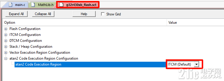
As a result, the critical CDE-accelerated angle-computation path runs from ITCM even when the project is built using the Flash configuration. This helps provide consistent execution time across different project configurations.
—
7. Benchmark Results
Before reviewing the measurements, it is important to clarify the comparison platform.
The G32R501 is also based on the Arm Cortex-M52 architecture, but it is positioned as a more feature-complete, performance-oriented real-time control MCU. Depending on the device configuration, it provides:
- Dual Arm Cortex-M52 cores running at up to 250 MHz
- Geehy’s proprietary Zidian Math Instruction Extension
- Arm Helium technology
- Single- and double-precision FPU support
- DSP support
The G32R430 follows a more specialized architecture, while the G32R501 provides a broader computing feature set. The following comparison is therefore intended to illustrate implementation paths and cycle-count ranges rather than serve as a strict apples-to-apples device benchmark.
7.1 Test Conditions
The measurements use the following conditions:
- Each platform uses its corresponding official example project
- Compiler optimization is set to
-O3
- Cycle counts are measured with the DWT cycle counter
- G32R430 results compare
ATAN2(..., 6) against a software-reference atan2
- Cross-platform results are used to compare general cycle-count ranges, not absolute performance under an identical software stack
- Test expression:
angle_param = PI / 65536.0 * idx * 4.0;
- Test range:
idx = -5 to 0
- G32R430 precision level:
6
7.2 Raw Measurement Screenshots
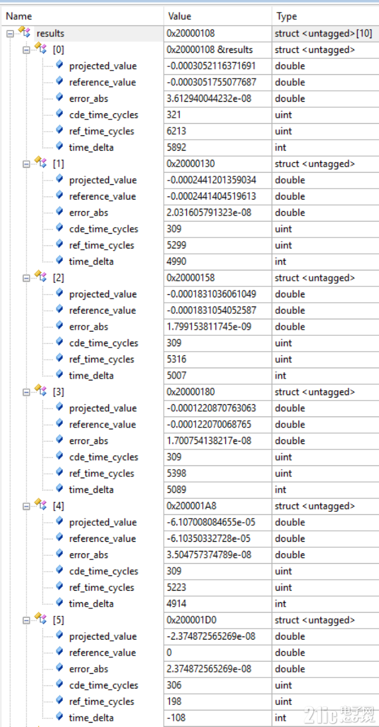
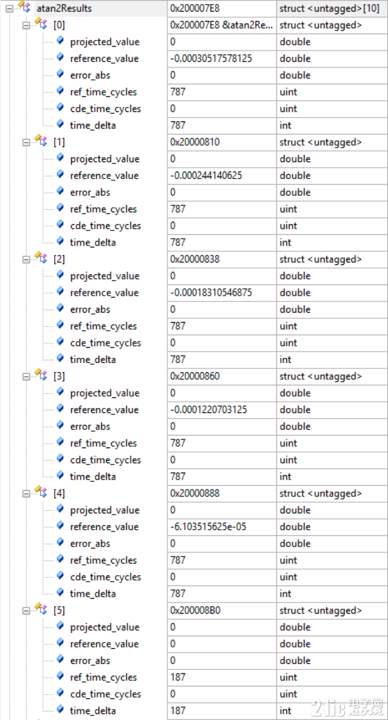
G32R430, Flash project, -O3:
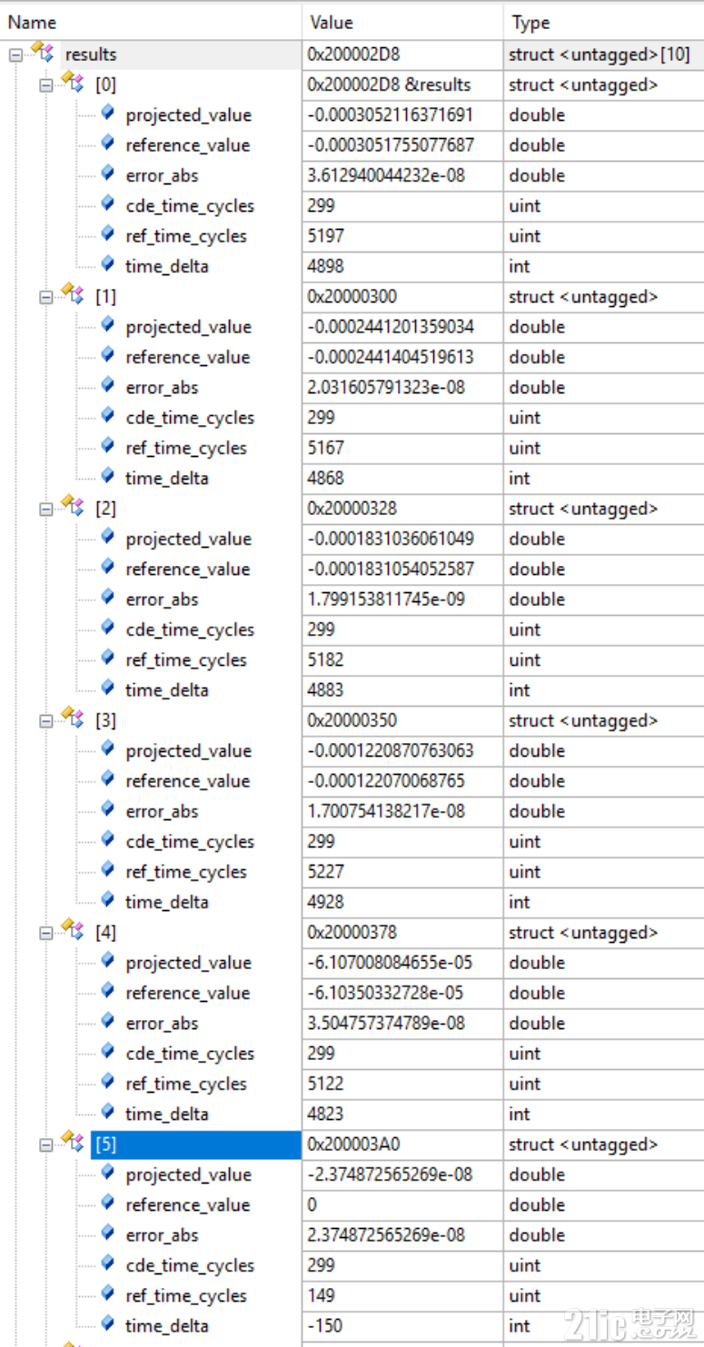
G32R430, ITCM/RAM project, -O3:
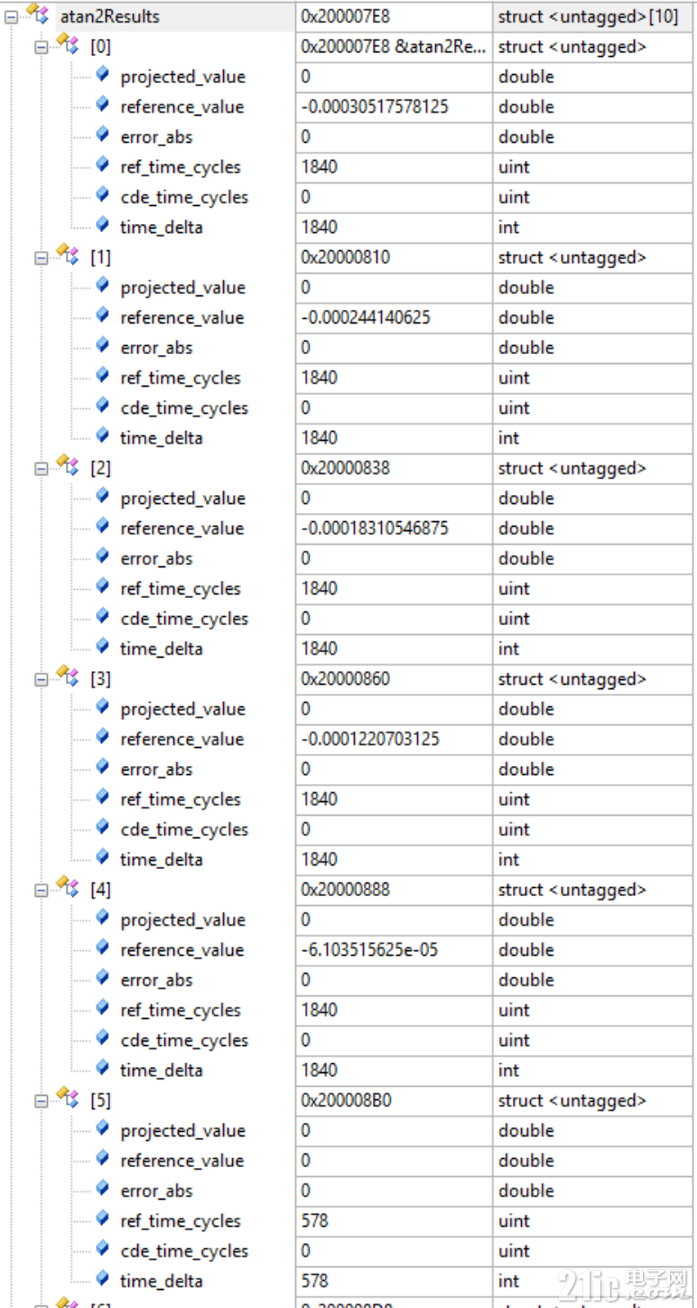
G32R501, CBUS Flash project, -O3, double-precision FPU path:
G32R501, ITCM/RAM project, -O3, double-precision FPU path:
7.3 Cycle-Count Comparison
| No. | angle_param (idx) | G32R430 Flash CDE (cycles) | G32R430 Flash reference (cycles) | G32R430 ITCM CDE (cycles) | G32R430 ITCM reference (cycles) | G32R501 Flash (cycles) | G32R501 ITCM (cycles) |
|---|
| 1 | PI / 65536 x (-5) x 4 | 321 | 6213 | 299 | 5197 | 1840 | 787 |
| 2 | PI / 65536 x (-4) x 4 | 309 | 5299 | 299 | 5167 | 1840 | 787 |
| 3 | PI / 65536 x (-3) x 4 | 309 | 5316 | 299 | 5182 | 1840 | 787 |
| 4 | PI / 65536 x (-2) x 4 | 309 | 5398 | 299 | 5227 | 1840 | 787 |
| 5 | PI / 65536 x (-1) x 4 | 309 | 5223 | 299 | 5122 | 1840 | 787 |
| 6 | idx = 0, angle approximately 0 | 306 | 198 | 299 | 149 | 578 | 187 |
For a more intuitive comparison, each result can be normalized against the G32R430 Flash CDE result at the same test point, which is defined as 1.0x.
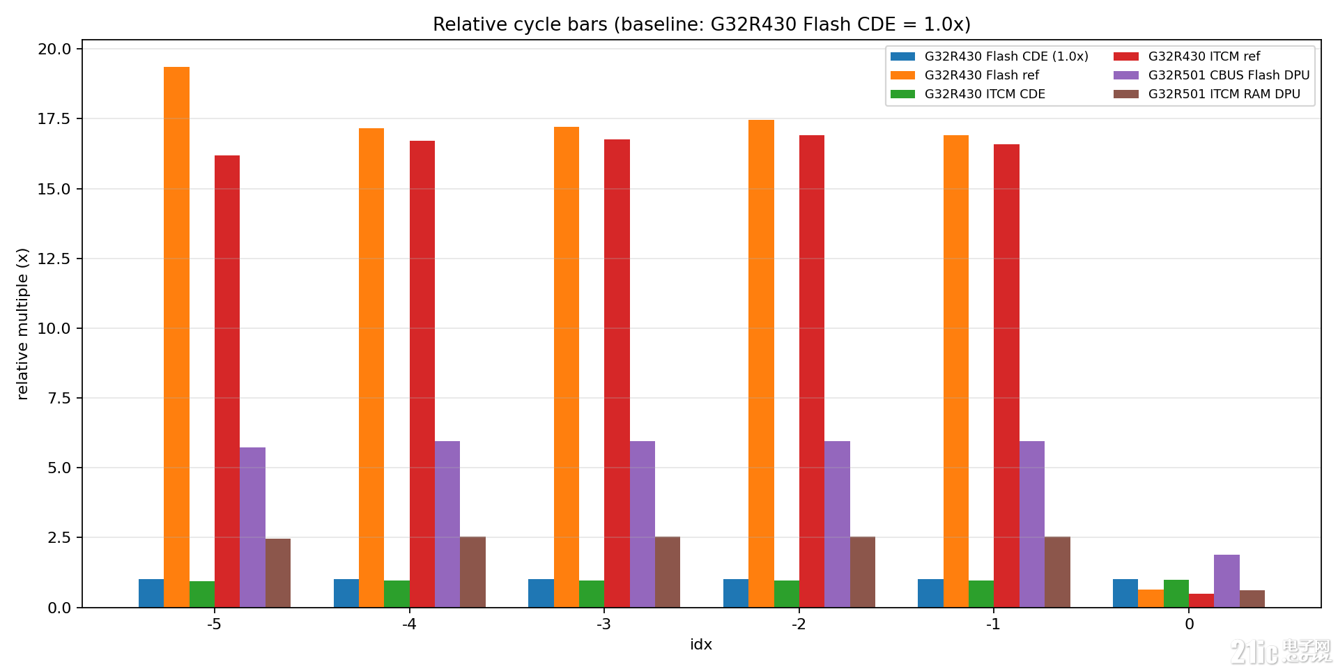
The chart shows that:
- The G32R430 Flash CDE path remains at the
1.0x baseline
- At the regular test points from
idx = -5 to idx = -1, the G32R430 Flash software-reference path requires approximately 16x to 19x as many cycles
- The G32R430 ITCM CDE result remains close to the Flash CDE result, indicating consistent execution across project configurations
- At
idx = 0, the software path becomes significantly faster because a special-case fast path is triggered
7.4 Interpreting the Results
For the regular angle points from test 1 to test 5:
- The G32R430 CDE path requires approximately
299 to 321 cycles
- The software-reference
atan2 implementation on the same device requires approximately 5,000 to 6,000 cycles
- The Flash CDE and ITCM CDE results are very close because the critical
ATAN2 code already executes from ITCM
- At
idx = 0, the software implementation becomes much faster, most likely because the special case atan2(0, 1) = 0 activates a short execution path
For a high-frequency interrupt service routine, consistent low latency is usually more valuable than an implementation that is fast only for specific input values.
—
8. Why Does the Manual Say 80 Cycles While the Table Shows More Than 300?
Most G32R430 CDE measurements in the comparison table are slightly above 300 cycles. This may appear inconsistent with the 80-cycle figure given for the hardware instruction.
The key is that the figures represent different measurement scopes.
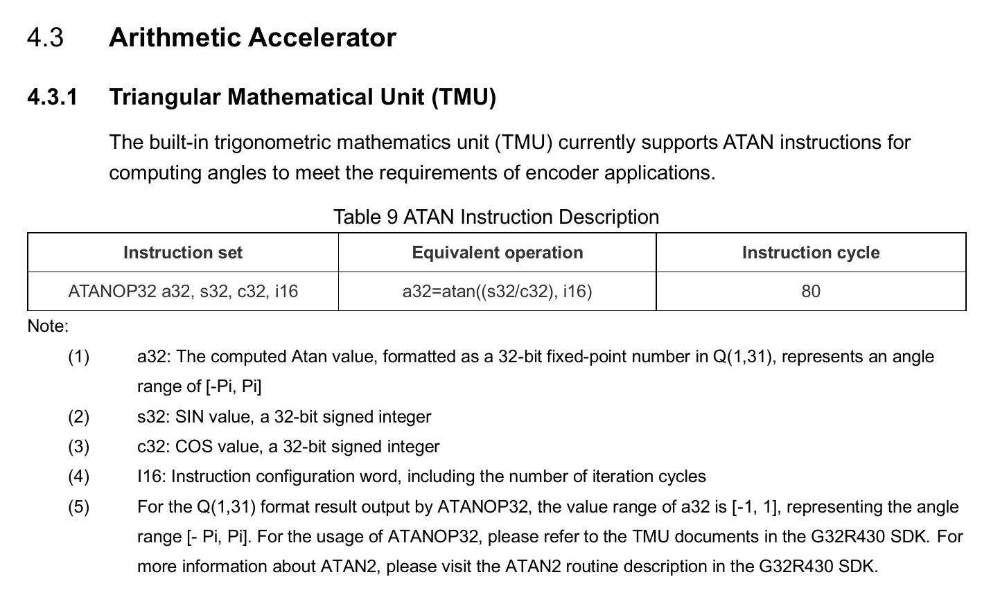
The user manual specifies the cycle count at the instruction level for the TMU ATANOP32 operation:
A separate microbenchmark can be used to isolate a single ATAN2 call with as little surrounding code as possible:
SECTION_DTCM_DATA uint32_t single_atan2_cycles = 0U;
SECTION_DTCM_DATA int32_t single_theta_q31 = 0;
SECTION_DTCM_DATA int32_t single_x_q30 =
double_to_q30(0.8660254037844386); /* cos(30 deg) */
SECTION_DTCM_DATA int32_t single_y_q30 =
double_to_q30(0.5); /* sin(30 deg) */
/**
* @brief Runs a standalone benchmark for one ATAN2 execution.
*
* @return None.
*/
void RunSingleAtan2Benchmark(void)
{
GET_DWT_CYCLE_COUNT(
single_atan2_cycles,
single_theta_q31 = ATAN2(
single_x_q30,
single_y_q30,
8
);
);
printf("Single ATAN2 benchmark:\n");
printf(
" Input (Q30): x=%d, y=%d\n",
single_x_q30,
single_y_q30
);
printf(
" Output (Q31 norm): %.10f\n",
q31_to_double(single_theta_q31)
);
printf(
" ATAN2 cycles: %lu\n\n",
(unsigned long)single_atan2_cycles
);
}
The serial output is shown below:
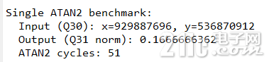
The three figures can therefore be understood as follows:
- Instruction-level figure:
80 cycles, as specified for the TMU ATANOP32 instruction
- Function-level microbenchmark: approximately
51 cycles for the minimal measured ATAN2(...) call path
- Example-level comparison: approximately
300+ cycles for the complete path used to align the hardware result with the software-reference result, including input preparation, measurement-macro overhead, and result conversion such as q31_to_double
These figures should not be treated as directly interchangeable because they describe different code paths and measurement boundaries.
For evaluating the ATAN2 function itself, use the isolated function-level benchmark. For understanding the documented instruction latency, refer to the instruction-level specification. The full example measurements are more suitable for comparing end-to-end implementation paths.
—
9. Selecting the Precision Level
The nPrecisionLevel parameter can be set from 1 to 8.
A practical selection strategy is:
- Start with level
6, which generally provides a good balance between speed and accuracy
- Use level
7 or 8 when the application has a tighter error budget
- Validate each setting in the closed loop because higher precision introduces additional execution overhead
The appropriate setting should be selected based on factors such as encoder resolution, control-loop bandwidth, and the application’s total angle-error budget.
The general rule is simple: meet the real-time deadline first, then increase precision where the system budget allows.
—
10. Key Takeaways
The benchmark highlights three main points:
- The G32R430 uses a dedicated hardware path instead of relying on a general-purpose floating-point unit
- Its fixed-point, CDE-accelerated
ATAN2 path reduces the complete example-level calculation to approximately 300 cycles, compared with roughly 5,000 to 6,000 cycles for the software-reference path at regular test points
- In high-frequency control loops, the architecture can provide improved real-time performance, more deterministic execution, and potential power-efficiency benefits
For encoder and single-axis servo applications, this is a practical design trade-off: even without an FPU, the G32R430 can still compute electrical angle quickly and consistently.
—
11. References
G32R430_DDL_SDK_V1.0.2/Libraries/ATAN2/MathLib.hG32R430_DDL_SDK_V1.0.2/Examples/Board_G32R430_Tiny/ATAN2/ATAN2_Math/