1. Introduction
Upon discovering the new APM32F411 TINY board on the Geehy official website, I was intrigued by its utilization of the Arm® Cortex®-M4F core and 55nm process technology. Boasting ample Flash, SRAM, and a rich set of on-chip peripherals, this product offers exceptional versatility and reliability.
For detailed MCU specifications, refer to the official website.
Fortunately, I now have the APM32F411 TINY board on hand, enabling me to gain initial experience.
2. Hardware Peripherals
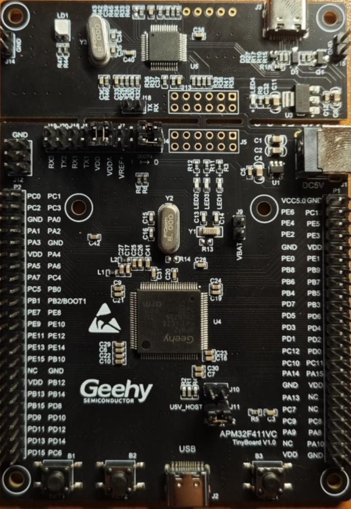
The board’s peripherals are illustrated in the image. The official website refers to this board as the TINY board, distinguishing it from the MINI board by the addition of a debugger (located above in the image). The specific peripherals are similar to the MINI board.

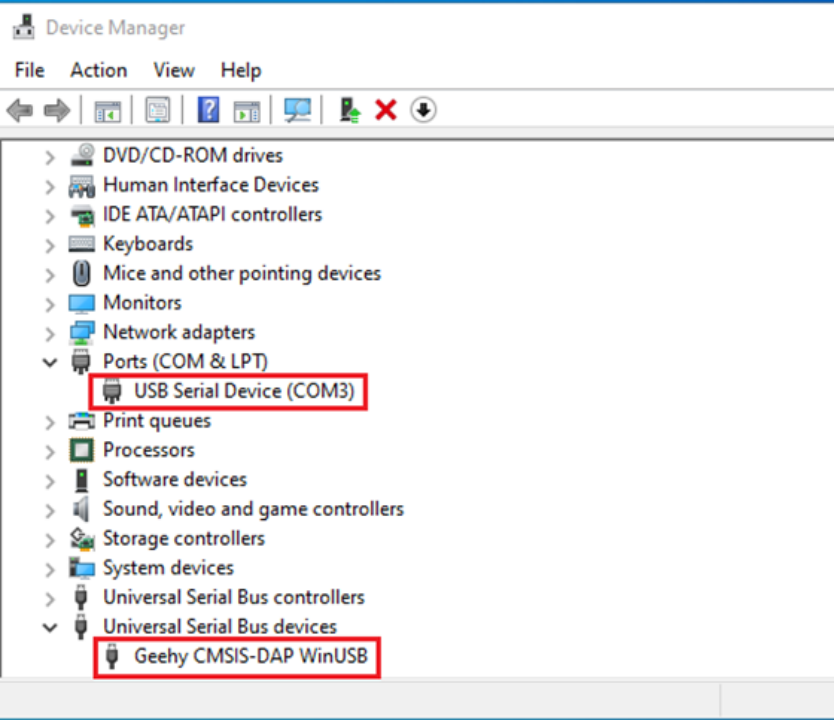
Connecting the Type-C port at the debugger of the TINY board to the computer, the device manager recognizes it as a WinUSB device. Simultaneously, the computer identifies a COM port.

This eliminates the need for an additional serial cable when using the serial port. The choice between using UART1 or UART2 is made through jumper cap connections.
With a general understanding of the APM32F411 TINY board’s hardware devices, the next step is to write and program code to observe the behavior.
3. Test Code Writing
Before writing the test code, download the latest Software Development Kit (SDK) for APM32F4 from the official website. The latest APM32F4 SDK includes interrupt vector information and system clock configuration for APM32F411. Since the system clock and interrupt vectors for APM32F411 differ from APM32F407, using the latest SDK facilitates test program writing.
For this, I’m using the Template example to write code for LED blinking and serial port printing.
Start by changing the project’s target to APM32F411 to ensure the system clock configuration and interrupt vectors are compatible with the APM32F411 model.

Next, refer to the onboard API functions provided by the official website and quickly write the code. The specific code is as follows:
int main(void)
{
APM_TINY_LEDInit(LED2);
APM_TINY_LEDInit(LED3);
USART_Config_T usartconfig;
USART_ConfigStructInit(&usartconfig);
usartconfig.baudRate = 115200;
APM_TINY_COMInit(COM1,&usartconfig);
printf("APM32F411 TINY TEST");
while (1)
{
APM_TINY_LEDOn(LED2);
The code initializes LED2, LED3, and the serial port, then prints information and turns on the LEDs.
With the code written, the next step is to burn the program into the board.
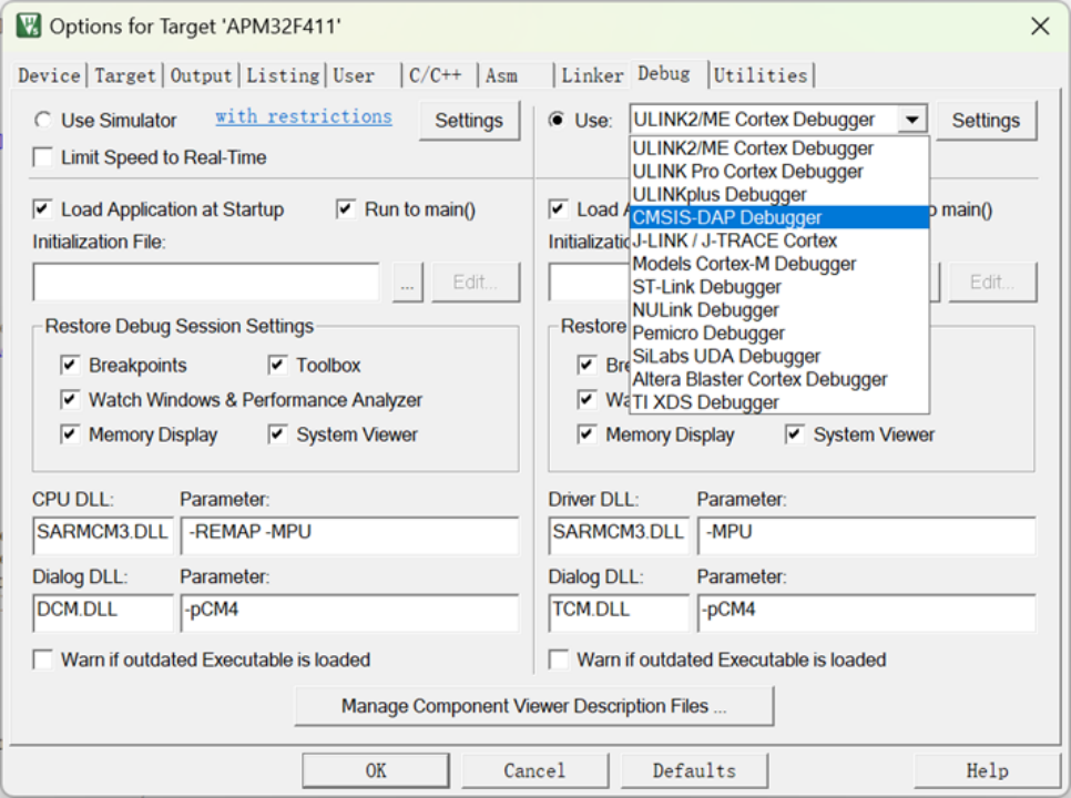
Check the device manager to confirm that the APM32F411 debugger is recognized as a CMSIS-DAP device. In the programming tool, choose Debug mode.

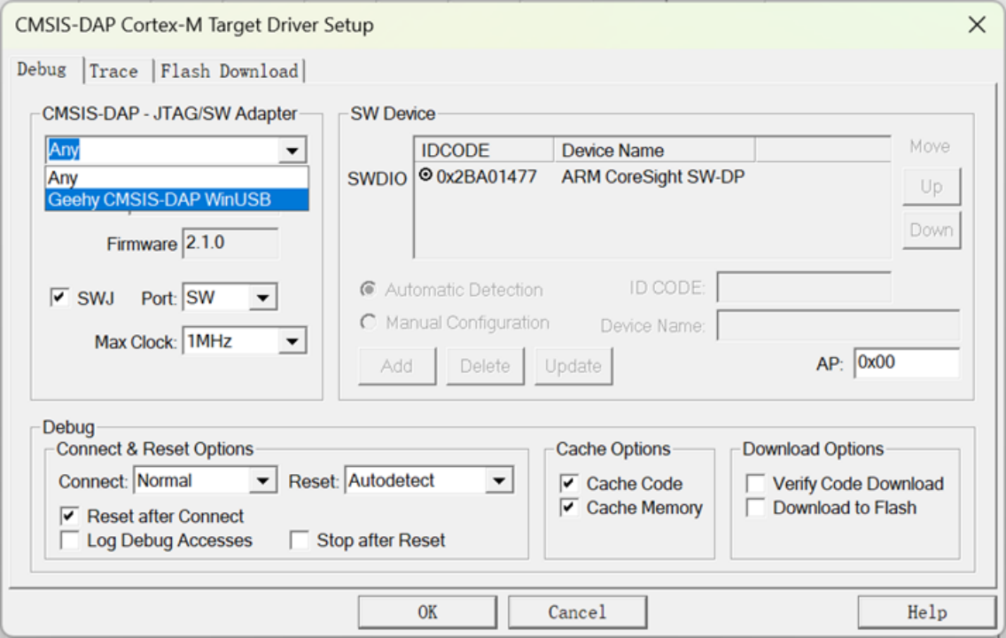
Select the recognized debugger’s name.

Finally, download the program.
4. Observations
After resetting the board, both LED lights successfully illuminate.
Opening a serial port tool, USART1 prints data successfully.
