*This content has been reposted with the approval of the original author.
Efficient ADC Sampling and DMA Transfer Implementation with TMR Trigger on TINY Board
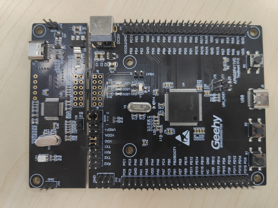
I recently delved into ADC sampling and decided to explore the integration of ADC, DMA, and TMR. My objective was to accomplish timed ADC sampling triggered by a timer and leverage DMA for efficient data transfer. Coincidentally, I acquired the APM32F411 development board, providing an ideal platform for implementing this functionality.
1. Intro to APM32F411

32-bit ARM Cortex-M4F core with FPU.
Supports a maximum operating frequency of 120MHz.
Flash capacity of 512KB+NVR, 32KB; SRAM capacity of 128KB.
Supports sleep, stop, and standby modes.
Supports CF card, SRAM, PSRAM, NOR, and NAND memory.
Features multiple communication peripherals and analog peripherals.
For more detailed information, visit their official website (https://geehy.com).
2. APM32F411 System Operating Frequency
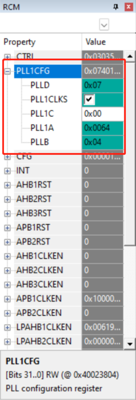
During debugging, I noticed that the official SDK for this chip sets the operating frequency to 100MHz instead of 120MHz. We can directly calculate the main frequency. Navigate to the Debug view, run to the main function, and open the RCM module view.

By checking the values in the PLL1CFG register and referring to the official manual’s calculation formula, we can determine the main frequency.

According to the manual, the actual system operating frequency is calculated as 8M * (100/4) / 2 = 100MHz. This has some impact on configuring TMR2 for timed triggering, so it’s essential to be aware of this.
3. Code
3.1 Timer
I selected TMR2 as the timer for triggering ADC sampling events. Specifically, by setting the TMR’s reload register to 1, one ADC data collection is triggered.

/*
Timer initialization
*/
void TMR_Init(void)
{
TMR_BaseConfig_T timBaseConfig;
// System operating frequency is 100M, as APB1 is divided by 2, so the time base calculation is as follows
timBaseConfig.period = 3; //Set timer time base to 4us,(3+1)*(99+1)/(50M*2) = 4us
timBaseConfig.division = 99;
timBaseConfig.clockDivision = TMR_CLOCK_DIV_1;
timBaseConfig.countMode = TMR_COUNTER_MODE_UP;
TMR_ConfigTimeBase(TMR2,&timBaseConfig);
//Choose an external trigger source
TMR_SelectOutputTrigger(TMR2, TMR_TRGO_SOURCE_UPDATE);
TMR_EnableInterrupt(TMR2,TMR_INT_UPDATE);
NVIC_EnableIRQRequest(TMR2_IRQn,0,0);
TMR_Enable(TMR2);
}
/*
TMR2 interrupt service function
*/
void TMR2_IRQHandler(void)
{
if (TMR_ReadIntFlag(TMR2, TMR_INT_UPDATE) != RESET)
{
TMR_ClearIntFlag(TMR2, TMR_INT_UPDATE);
if(count)
{
count--;
}
else
{
//Timer 1s, print data once
count = 250000;
if(DMA_ReadCurrentMemoryTarget(DMA2_Stream0))
{
printf("The memory currently accessed by DMA : 1 \r\n");
printf("Volatage = %.2f V\r\n",(double)adc_data[1][0]/4096*3.3);
}
else
{
printf("The memory currently accessed by DMA : 0 \r\n");
printf("Volatage = %.2f V\r\n",(double)adc_data[0][0]/4096*3.3);
}
APM_TINY_LEDToggle(LED2);
}
}
}
3.2 ADC
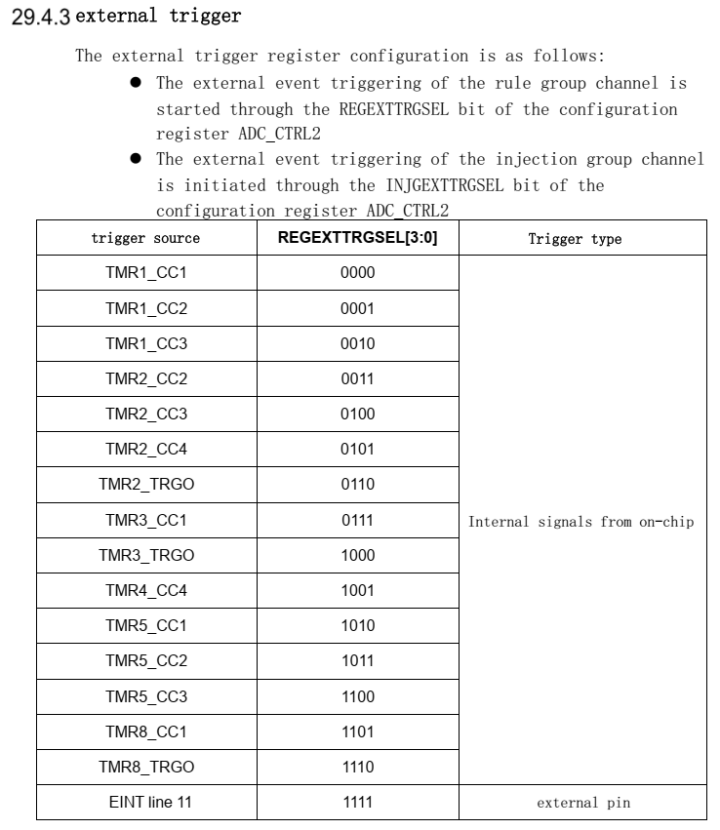
The APM32F411 has two ADC sources; I’m utilizing ADC1 and configuring it for TMR2 triggering. Now, let’s refer to the official manual for details on ADC external triggering.

/**
Initialization code
*/
void ADC_Init(void)
{
ADC_Config_T adcConfig;
ADC_CommonConfig_T adcCommonConfig;
ADC_Reset();
/*
ADC Sampling: 50M, (112+12)/50M = 2.48us, 2.48us for one ADC sampling
*/
adcCommonConfig.accessMode = ADC_ACCESS_MODE_DISABLED;//ADC does not use direct access DMA mode
adcCommonConfig.mode = ADC_MODE_INDEPENDENT; //Comfiture ADC to independent mode
adcCommonConfig.prescaler = ADC_PRESCALER_DIV2; //ADC 2 division:100M/2=50M
adcCommonConfig.twoSampling = ADC_TWO_SAMPLING_5CYCLES; //Delay between 2 sampling phases: Only used in double or triple interleaved mode
ADC_CommonConfig(&adcCommonConfig);
adcConfig.resolution = ADC_RESOLUTION_12BIT;//Configure ADC resolution
adcConfig.scanConvMode = DISABLE;//Disable ADC loop scan mode
adcConfig.continuousConvMode = DISABLE;//Configure ADC single conversion mode; otherwise, except for the first time triggered by external TMR, the rest are software-triggered
adcConfig.extTrigEdge = ADC_EXT_TRIG_EDGE_RISING; //Configure ADC external rising edge trigger
adcConfig.extTrigConv = ADC_EXT_TRIG_CONV_TMR2_TRGO;//Configure ADC to use TMR2 trigger
adcConfig.dataAlign = ADC_DATA_ALIGN_RIGHT; //ADC data right alignment
adcConfig.nbrOfChannel = 1; //Configure the number of ADC conversion channels
ADC_Config(ADC1, &adcConfig);
ADC_ConfigRegularChannel(ADC1, ADC_CHANNEL_0, 1, ADC_SAMPLETIME_112CYCLES);
ADC_EnableDMA(ADC1);
ADC_EnableDMARequest(ADC1);
ADC_Enable(ADC1);
}
3.3 DMA
I’m using one ADC route and one channel to transfer data to DMA. It’s also possible to transfer data from multiple ADC channels with slight modifications to the DMA program and define additional data spaces.
/*DMA initialization*/
void DMA_Configuration(void)
{
DMA_Config_T dmaConfig;
DMA_Reset(DMA2_Stream0);
dmaConfig.channel = DMA_CHANNEL_0;
dmaConfig.peripheralBaseAddr = (uint32_t) & (ADC1->REGDATA);//DMA peripheral base address configuration as ADC1 data register
dmaConfig.memoryBaseAddr = (uint32_t)adc_data[0];//DMA main storage base address configuration
dmaConfig.dir = DMA_DIR_PERIPHERALTOMEMORY;//DMA transfer direction: peripheral -> memory
dmaConfig.bufferSize = 1;
dmaConfig.peripheralInc = DMA_PERIPHERAL_INC_DISABLE;//DMA peripheral base address does not increment
dmaConfig.memoryInc = DMA_MEMORY_INC_ENABLE;//DMA main storage base address increments
dmaConfig.peripheralDataSize = DMA_PERIPHERAL_DATA_SIZE_HALFWORD;// DMA transfers in half-word units
dmaConfig.memoryDataSize = DMA_MEMORY_DATA_SIZE_HALFWORD;
dmaConfig.loopMode = DMA_MODE_NORMAL;//Configure DMA to NORMAL mode, meaning DMA starts transferring when external TMR triggers ADC sampling
dmaConfig.priority = DMA_PRIORITY_HIGH;
dmaConfig.fifoMode = DMA_FIFOMODE_DISABLE;
dmaConfig.fifoThreshold = DMA_FIFOTHRESHOLD_HALFFULL;
dmaConfig.memoryBurst = DMA_MEMORYBURST_SINGLE;
dmaConfig.peripheralBurst = DMA_PERIPHERALBURST_SINGLE;
DMA_Config(DMA2_Stream0, &dmaConfig);
//Enable DMA double-buffer mode
DMA_ConfigBufferMode(DMA2_Stream0,(uint32_t)adc_data[1],DMA_MEMORY_0);
DMA_EnableDoubleBufferMode(DMA2_Stream0);
DMA_Enable(DMA2_Stream0);
//Enable DMA completion interrupt
DMA_EnableInterrupt(DMA2_Stream0,DMA_INT_TCI**);
NVIC_EnableIRQRequest(DMA2_STR0_IRQn,0,0);
}
/*
DMA_Stream0 interrupt service function
*/
void DMA2_STR0_IRQHandler(void)
{
if(DMA_ReadIntFlag(DMA2_Stream0,DMA_INT_TCI**0) != RESET)
{
DMA_ClearIntFlag(DMA2_Stream0,DMA_INT_TCI**0);
}
}
4. Main Function
volatile uint32_t adc_data[2][1]; //Store ADC collected data
void RCM_Init(void);
void GPIO_Init(void);
void TMR_Init(void);
void ADC_Init(void);
void DMA_Configuration(void);
volatile uint32_t count = 250000;
/*
Clock initialization
*/
void RCM_Init(void)
{
RCM_EnableAHB1PeriphClock(RCM_AHB1_PERIPH_DMA2 | RCM_AHB1_PERIPH_GPIOA);
RCM_EnableAPB2PeriphClock(RCM_APB2_PERIPH_ADC1);
RCM_EnableAPB1PeriphClock(RCM_APB1_PERIPH_TMR2);
}
/*
GPIO initialization
*/
void GPIO_Init(void)
{
GPIO_Config_T gpioConfig;
gpioConfig.pin = GPIO_PIN_0;
gpioConfig.mode = GPIO_MODE_AN;
gpioConfig.pupd = GPIO_PUPD_NOPULL;
GPIO_Config(GPIOA, &gpioConfig);
}
int main(void)
{
USART_Config_T usartConfig;
usartConfig.baudRate = 115200;
usartConfig.hardwareFlow = USART_HARDWARE_FLOW_NONE;
usartConfig.mode = USART_MODE_TX_RX;
usartConfig.parity = USART_PARITY_NONE;
usartConfig.stopBits = USART_STOP_BIT_1;
usartConfig.wordLength = USART_WORD_LEN_8B;
USART_Config(USART1,&usartConfig);
APM_TINY_COMInit(COM1,&usartConfig);
APM_TINY_LEDInit(LED2);
RCM_Init();
GPIO_Init();
TMR_Init();
ADC_Init();
DMA_Configuration();
while (1)
{
}
}[upl-image-preview url=https://community.geehy.com/assets/files/2023-12-25/1703494939-328477-image.png]
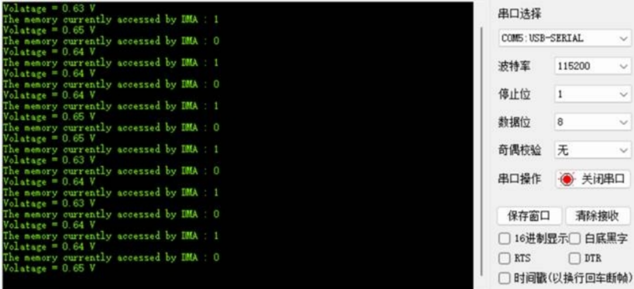
5. Running Effect
