Hi Chaos…
yes i want adc clock derived from pclk,,, i hv also enabled adc jitter,,, my source code is as in follows sequence,,,
SetSysClock();
GPIO_Init();
ADC_Init();
void SetSysClock() {
RCM_Reset();
RCM_ConfigSYSCLK(RCM_SYSCLK_SEL_HSI);
RCM_DisablePLL(); /* Disable PLL /
while (RCM->CTRL1_B.PLLRDYFLG == SET); / Wait until Pll is ready */
RCM_ConfigPLL(RCM_PLL_SEL_HSI_DIV2, RCM_PLLMF_8);
RCM_EnablePLL(); /* Enable PLL /
RCM_ConfigSYSCLK(RCM_SYSCLK_SEL_PLL); / Selct PLL as Sysclk */
RCM_ConfigAHB(RCM_SYSCLK_DIV_2);
RCM_ConfigAPB(RCM_HCLK_DIV_1);
FMC_SetLatency(FMC_LATENCY_1);
RCM_EnableAPB2PeriphClock(RCM_APB2_PERIPH_SYSCFG);
RCM_EnableAHBPeriphClock(RCM_AHB_PERIPH_GPIOA);
RCM_EnableAHBPeriphClock(RCM_AHB_PERIPH_GPIOB);
RCM_EnableAPB2PeriphClock(RCM_APB2_PERIPH_ADC1);
RCM_EnableAPB1PeriphClock(RCM_APB1_PERIPH_TMR3);
RCM_EnableAPB1PeriphClock(RCM_APB1_PERIPH_TMR14);
}
void GPIO_Init () {
GPIO_Config_T gpioConfig;
// configure pa1, pa2, pa3 pins as anlog input pins
gpioConfig.mode = GPIO_MODE_AN;
gpioConfig.pupd = GPIO_PUPD_NO;
gpioConfig.pin = GPIO_PIN_1 | GPIO_PIN_2 | GPIO_PIN_3;
GPIO_Config(GPIOA, &gpioConfig);
// configure lcd port pins
gpioConfig.pin = D7_Pin | D6_Pin | D5_Pin | D4_Pin | EN_Pin;
gpioConfig.mode = GPIO_MODE_OUT;
gpioConfig.outtype = GPIO_OUT_TYPE_PP;
gpioConfig.speed = GPIO_SPEED_10MHz;
gpioConfig.pupd = GPIO_PUPD_PU;
GPIO_Config(GPIOB, &gpioConfig);
gpioConfig.pin = RW_Pin | RS_Pin ;
gpioConfig.mode = GPIO_MODE_OUT;
gpioConfig.outtype = GPIO_OUT_TYPE_PP;
gpioConfig.speed = GPIO_SPEED_10MHz;
gpioConfig.pupd = GPIO_PUPD_PU;
GPIO_Config(GPIOA, &gpioConfig);
// set all output pins to 0
GPIO_ClearBit(RW_GPIO_Port,RW_Pin);
GPIO_ClearBit(RS_GPIO_Port,RS_Pin);
GPIO_ClearBit(EN_GPIO_Port,EN_Pin);
GPIO_ClearBit(D7_GPIO_Port,D7_Pin);
GPIO_ClearBit(D6_GPIO_Port,D6_Pin);
GPIO_ClearBit(D5_GPIO_Port,D5_Pin);
GPIO_ClearBit(D4_GPIO_Port,D4_Pin);
}
void ADC_Init() {
ADC_Config_T adcConfig;
ADC_Reset();
ADC_ClockMode(ADC_CLOCK_MODE_SYNCLKDIV4);
ADC_EnableJitter(ADC_JITTER_PCLKDIV4);
ADC_ConfigStructInit(&adcConfig);
adcConfig.resolution = ADC_RESOLUTION_12B;
adcConfig.scanDir = ADC_SCAN_DIR_UPWARD;
adcConfig.convMode = ADC_CONVERSION_SINGLE;
adcConfig.dataAlign = ADC_DATA_ALIGN_RIGHT;
adcConfig.extTrigConv = ADC_EXT_TRIG_CONV_TRG0;
adcConfig.extTrigEdge = ADC_EXT_TRIG_EDGE_NONE;
ADC_Config(&adcConfig);
ADC_ReadCalibrationFactor();
ADC_Enable();
while (!ADC_ReadStatusFlag(ADC_FLAG_ADRDY)) {};
}
the output on lcd is as attached…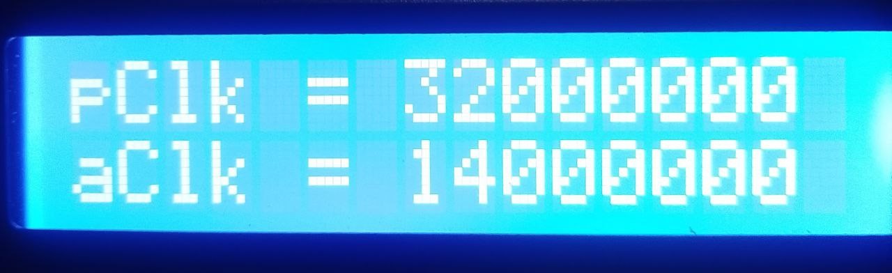
pl suggest how to modify clock to adc module…
thanks a lot…
John