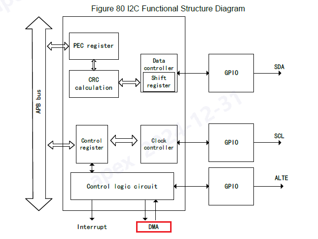
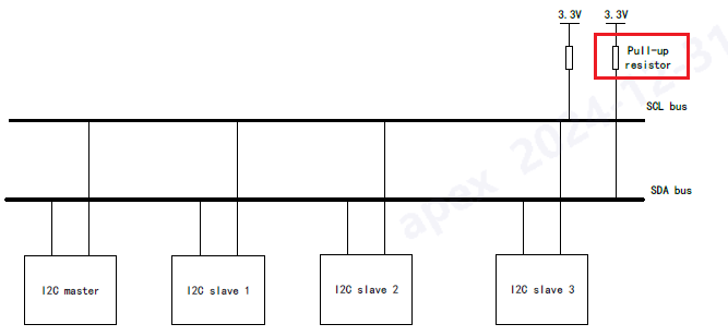
I2C is a short-distance bus communication protocol. In physical implementation, I2C bus is composed of two signal lines (SDA and SCL) and a ground wire. These two signal lines can be used for bidirectional transmission.
Two signal lines, SCL clock line and SDA data line. SCL provides timing for SDA, and SDA transmits/receives data in series
Both SCL and SDA signal lines are bidirectional
The ground is common when the two systems use I2C bus for communication

The I2C peripherals on APM32F4xx devices have master & slave function, integrate 7-bit and 10-bit addressing mode, and support both standard mode (100kHz) and fast mode (400kHz and 1MHz) protocols.

The set-up time and duty cycle can be programmed too, while it is not highly flexible, please notice that the duty cycle for Fast Mode is whether 2 or 16/9.
According to the software process of I2C, when the transmit register is empty or the receive register is full, MCU needs to write or read bytes, then we can complete the operation more quickly through the DMA function of I2C.
_DMA transmission
Set the DMAEN bit in I2C_CTRL2 register to enabe the DMA mode. When the transmit register is empty (TXBEFLG is set to 1), the data will be directly loaded from the memory area to the DATA register through DMA.
DMA receiving
Set DMAEN in I2C_CTRL2 register to enable DMA mode. When the receiving register is full (RXBNEFLG is set to 1), DMA will transmit DATA register data to the set storage area._
This is the reference code based on APM324xx standard peripheral library.
// SCL:PB10, SDA:PB11 (RX:DMA1_STREAM3_CH7)
void I2C2_Init(void)
{
GPIO_Config_T gpioConfigStruct;
I2C_Config_T i2cConfigStruct;
/* Enable I2C related Clock */
RCM_EnableAHB1PeriphClock(RCM_AHB1_PERIPH_GPIOB);
RCM_EnableAPB1PeriphClock(RCM_APB1_PERIPH_I2C2);
/* Free I2C_SCL and I2C_SDA */
GPIO_ConfigPinAF(GPIOB, GPIO_PIN_SOURCE_10, GPIO_AF_I2C2);
GPIO_ConfigPinAF(GPIOB, GPIO_PIN_SOURCE_11, GPIO_AF_I2C2);
gpioConfigStruct.mode = GPIO_MODE_AF;
gpioConfigStruct.speed = GPIO_SPEED_50MHz;
gpioConfigStruct.pin = GPIO_PIN_10 | GPIO_PIN_11;
gpioConfigStruct.otype = GPIO_OTYPE_OD;
gpioConfigStruct.pupd = GPIO_PUPD_NOPULL;
GPIO_Config(GPIOB, &gpioConfigStruct);
/* Config I2C2 */
I2C_Reset(I2C2);
i2cConfigStruct.mode = I2C_MODE_I2C;
i2cConfigStruct.dutyCycle = I2C_DUTYCYCLE_2;
i2cConfigStruct.ackAddress = I2C_ACK_ADDRESS_7BIT;
i2cConfigStruct.ownAddress1 = 0XA0;
i2cConfigStruct.ack = I2C_ACK_ENABLE;
i2cConfigStruct.clockSpeed = 400000;//1000000;
I2C_Config(I2C2, &i2cConfigStruct);
/** Enable I2C */
I2C_Enable(I2C2);
}
And regarding the DMA configuration:
void I2C2_DMA_Init(uint8_t* RxBuf)
{
/* DMA Configure */
DMA_Config_T dmaConfigStruct;
RCM_EnableAHB1PeriphClock(RCM_AHB1_PERIPH_DMA1);
NVIC_EnableIRQRequest(DMA1_STR3_IRQn, 0, 0);
DMA_ClearStatusFlag(DMA1_Stream3, DMA_FLAG_FEIFLG7 | DMA_FLAG_DMEIFLG7 | DMA_FLAG_TEIFLG7 | DMA_FLAG_HTIFLG7 | DMA_FLAG_TCIFLG7);
DMA_Disable(DMA1_Stream3);
DMA_Reset(DMA1_Stream3);
dmaConfigStruct2.channel = DMA_CHANNEL_7;
dmaConfigStruct2.peripheralBaseAddr = (uint32_t)&I2C2->DATA;
dmaConfigStruct2.memoryBaseAddr = (uint32_t)RxBuf;
dmaConfigStruct2.dir = DMA_DIR_PERIPHERALTOMEMORY;
dmaConfigStruct2.bufferSize = 0xFFFF;
dmaConfigStruct2.peripheralInc = DMA_PERIPHERAL_INC_DISABLE;
dmaConfigStruct2.memoryInc = DMA_MEMORY_INC_ENABLE;
dmaConfigStruct2.peripheralDataSize = DMA_PERIPHERAL_DATA_SIZE_BYTE;
dmaConfigStruct2.memoryDataSize = DMA_MEMORY_DATA_SIZE_BYTE;
dmaConfigStruct2.loopMode = DMA_MODE_NORMAL;
dmaConfigStruct2.priority = DMA_PRIORITY_VERYHIGH;
dmaConfigStruct2.fifoMode = DMA_FIFOMODE_ENABLE;
dmaConfigStruct2.fifoThreshold = DMA_FIFOTHRESHOLD_FULL;
dmaConfigStruct2.memoryBurst = DMA_MEMORYBURST_SINGLE;
dmaConfigStruct2.peripheralBurst = DMA_PERIPHERALBURST_SINGLE;
DMA_Config(DMA1_Stream3, &dmaConfigStruct2);
DMA_EnableInterrupt(DMA1_Stream3, **DMA_INT_TCIFLG**);
I2C_EnableDMA(I2C2);
}
Under this configuration, you are free to call any I2C functions that the SDK supports, like, I2C_EnableGenerateStop; I2C_EnableGenerateStart; I2C_Tx7BitAddress; I2C_TxData; I2C_RxData; I2C_EnableAcknowledge.
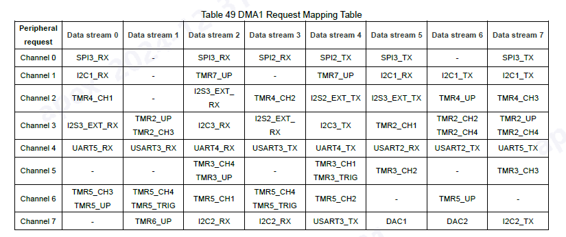
To allow single DMA transmission, DMA interrupt on the corresponding stream is required. For example, I’m choosing DMA1 Stream3 Channel7 as I2C2_RX channel.
void DMA1_STR3_IRQHandler(void)
{
if(DMA_ReadStatusFlag(DMA1_Stream3, DMA_INT_TCIFLG3) != RESET)
{
I2C_EnableGenerateStop(I2C2);
DMA_Disable(DMA1_Stream3);
DMA_ClearStatusFlag(DMA1_Stream3, DMA_INT_TCIFLG3);
TxRxDataSizeI2C2 = 0;
}
APM_MINI_LEDToggle(LED3);
}
Please notice, in the header file of the SDK, two types of DMA Flags are designed, and only DMA_INT_FLAG_T is the correct parameter for DMA_ReadStatusFlag() and DMA_ClearStatusFlag().
The DMA status is related to the DMA stream, not the channel, which is most likely to confuse about.
