APM32 MCU runaway? Crash? Hardfault?
Don’t know what to do when encountering these unexpected scenarios? An expert would think of using J-Link commander to query information, can you? Today, I will introduce several common commands for the J-Link commander tool to help you master the APM32 chip smoothly.

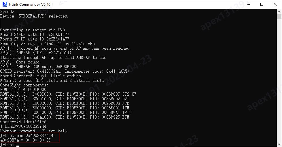
1. mem: Read memory by byte
Command format: mem <address> <number of bytes>.
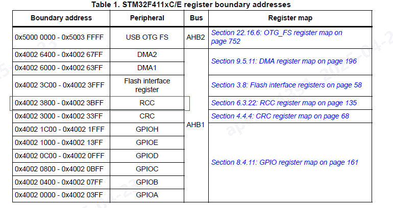
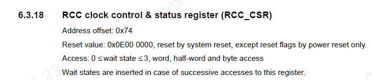
For example, with the APM32F411 chip, to read the RCC clock control & status register at address 0×40023800+0×74, you would enter: mem 0×40023874 4.
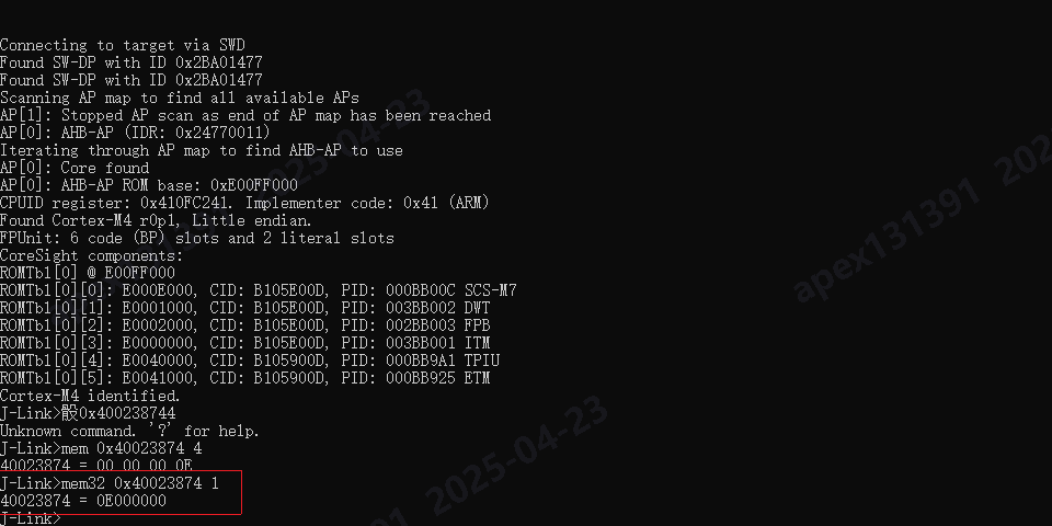
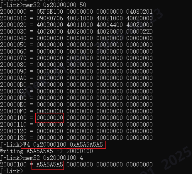
2. mem32: Read memory by word (4 bytes)
Command format: mem32 <address> <number of words>.
For example, with the APM32F411 chip, to read the RCC clock control & status register at address 0×40023800+0×74, you would enter: mem32 0×40023874 1.
3. W4: Write memory by word (4 bytes)
Command format: W4 <address> <data to write>.
For example, with the APM32F411 chip, to write the data 0xA5A5A5A5 to the SRAM address 0×20000100, you would enter: W4 0×20000100 0xA5A5A5A5.
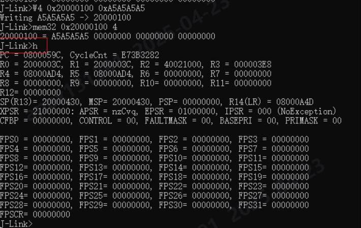
4. h: Halt
This stops the CPU execution. After entering this command, you can check information such as the PC pointer.
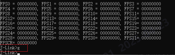
5. g: Go
The CPU starts running at full speed after this command is entered. If your development board has an LED, you will see the program running and the light blinking.
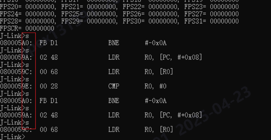
6. s: Single Step
When this command is entered, the CPU will execute one assembly instruction. (Note: The single-step command can only be used when the CPU is in a Halt state. This means you must call the “h” command before using single-step.)
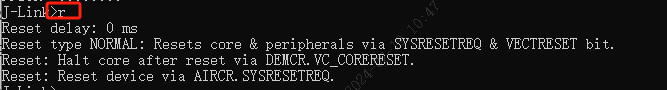
7. r: Reset CPU
Entering this command will cause the MCU to reset, and the program will restart from the beginning.
Summary of common commands:
- usb: Connect to the target board
- r: Restart the target board
- halt: Stop the program running on the CPU
- loadbin: Load an executable binary file
- g: Jump to the code segment address and execute
- s: Single step execution (for debugging)
- setpc: Set the value of the PC register (for debugging)
- setbp: Set a breakpoint
- Regs: Read the register set; this command displays all registers
- wreg: Write to a register
- mem: Read memory
- w4: Write memory
- power off mmu: Disable the MMU, which is very important for bare-metal debugging
- w4 cpsr, 0×0000001f: Switch to system mode
- speed: Set the JTAG transmission speed
- rce 0,c0,c0,0: Set the first register of CP15 to 0
Less common commands:
Here are some less common commands for those who are interested:
- ite: Read 32-bit items from memory. Syntax:
w4 <addr>, <num> (reads 32 bytes from memory)
- wm: Write test words. Syntax:
wm
- is: Identify the length of the scan chain select register
- ms: Measure the length of the scan chain. Syntax:
ms
- mr: Measure RTCK reaction time. Syntax:
mr
- q: Quit
- qc: Close J-Link connection and quit
- r: Reset target (RESET)
- rx: Reset target (RESET) with delay. Syntax:
rx <delay>
- RSetType: Set the current reset type. Syntax:
RSetType <type>
- Regs: Display contents of registers
- wreg: Write to a register. Syntax:
wreg <RegName>, <Value>
- SetBP: Set a breakpoint. Syntax:
SetBP <addr> [A/T] [S/H]
- SetWP: Set a watchpoint. Syntax:
SetWP <addr> [R/W] [<Data> [<A-Mask>]]
- ClrBP: Clear a breakpoint. Syntax:
ClrBP <BPHandle>
- ClrWP: Clear a watchpoint.
- VCatch: Write vector catch. Syntax:
VCatch <value>
- loadbin: Load a binary file into target memory. Syntax:
loadbin <filename>, <addr>
- savebin: Save target memory into a binary file. Syntax:
savebin <filename>, <addr>, <numbytes>
- SetPC: Set the PC to a specified value. Syntax:
SetPC <addr>
- le: Change to little-endian mode
- be: Change to big-endian mode
- log: Enable logging to a file. Syntax:
log <filename>