Introduction
Recently, I researched the method for adding unsupported devices to newer versions of the J-Link driver. I have organized the information and written this note as a record.
This guide is based on the “Open Flashloader” chapter of the UM08001_JLink document (found in JLink_V780b and earlier; later versions use a web link) and the “J-Link Device Support Kit” section on the SEGGER Wiki.
The method for adding a device is to add an XML file to the JLinkDevices directory at a specific path.
JLinkDevices Path
The path for JLinkDevices in different operating systems is as follows:
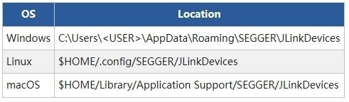
If the JLinkDevices directory does not exist, you need to create it manually.
JLinkDevices Directory Structure
The officially recommended directory structure for JLinkDevices is as follows:
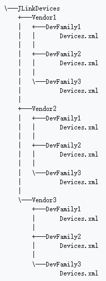
Here, Vendor represents the manufacturer, DevFamily represents the device series, and Devices represents the specific devices.
Since J-Link treats all XML files within the JLinkDevices directory as part of the device database, you can also manage devices using a single JLinkDevices.xml file, similar to older versions.
XML File
To add a device, you need to edit an XML file. The XML has four main elements:
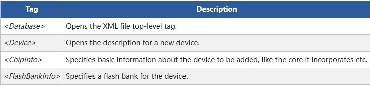
- <Database>: The root element of the XML file. An XML file can only have one <Database>.
- <Device>: Describes the new device. This element has no attributes.
- <ChipInfo>: A sub-element of <Device>, used to describe the basic information of the device.
- <FlashBankInfo>: A sub-element of <Device>, used to describe the Flash Bank information of the device.
The general format of the XML file is as follows:
<Database>
<Device>
<ChipInfo
Vendor="My Vendor"
Name="My Device1524"
WorkRAMAddr="0x20000000"
WorkRAMSize="0x10000"
Core="JLINK_CORE_CORTEX_M0"
/>
<FlashBankInfo
Name="My Flash Bank1"
BaseAddr="0x08000000"
AlwaysPresent="1"
>
<LoaderInfo
Name="My Flash loader"
MaxSize="0x30000"
Loader="Device_128.FLM"
LoaderType="FLASH_ALGO_TYPE_OPEN"
/>
</FlashBankInfo>
</Device>
</Database>
ChipInfo
ChipInfo is used to describe the basic information of the device, such as the vendor name, device name, etc. The attributes are as follows:
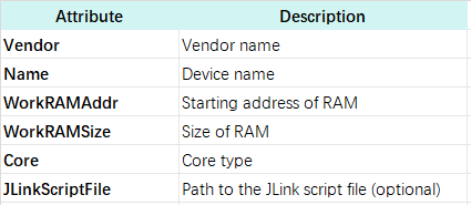
The Core attribute requires a parameter from a specific range defined by J-Link. Common parameters include:
- JLINK_CORE_CORTEX_M1
- JLINK_CORE_CORTEX_M3
- JLINK_CORE_CORTEX_M0
- JLINK_CORE_CORTEX_M4
- JLINK_CORE_CORTEX_M7
- JLINK_CORE_CORTEX_M23
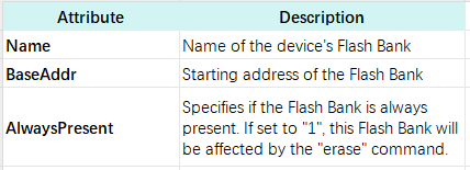
FlashBankInfo
FlashBankInfo is used to describe the device’s Flash Bank information. Its attributes are as follows:
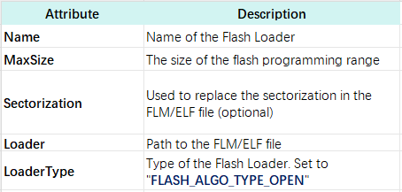
FlashBankInfo also has a sub-element, <LoaderInfo>, which describes the Flash Loader for that Flash Bank. Its attributes are as follows:
Addition Demonstration
Next, we will demonstrate adding a new device named “My Device”.
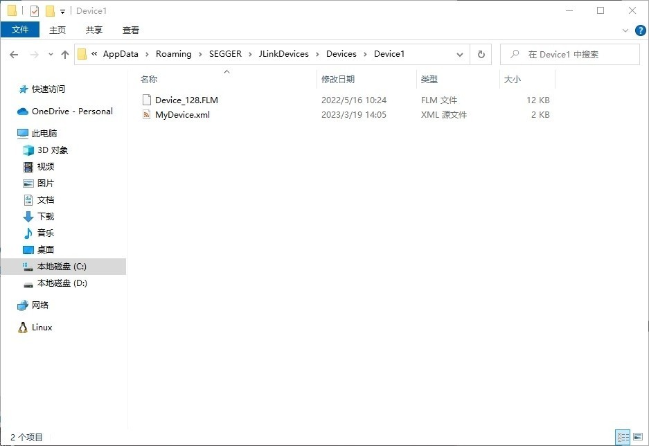
First, prepare the directory for the new device under /AppData/Roaming/SEGGER/JLinkDevices and add the FLM flash algorithm file and the XML file to it.
Add the following device description to the XML file:
<Database>
<Device>
<ChipInfo
Vendor="My Vendor"
Name="My Device1524"
WorkRAMAddr="0x20000000"
WorkRAMSize="0x10000"
Core="JLINK_CORE_CORTEX_M0"
/>
<FlashBankInfo
Name="My Flash Bank1"
BaseAddr="0x08000000"
AlwaysPresent="1"
>
<LoaderInfo
Name="My Flash loader"
MaxSize="0x10000"
Loader="Device_128.FLM"
LoaderType="FLASH_ALGO_TYPE_OPEN"
/>
</FlashBankInfo>
<FlashBankInfo
Name="My Flash Bank2"
BaseAddr="0x08010000"
AlwaysPresent="1"
>
<LoaderInfo
Name="My Flash loader"
MaxSize="0x10000"
Loader="Device_128.FLM"
LoaderType="FLASH_ALGO_TYPE_OPEN"
/>
</FlashBankInfo>
<FlashBankInfo
Name="My Flash Bank3"
BaseAddr="0x08020000"
AlwaysPresent="1"
>
<LoaderInfo
Name="My Flash loader"
MaxSize="0x10000"
Loader="Device_128.FLM"
LoaderType="FLASH_ALGO_TYPE_OPEN"
/>
</FlashBankInfo>
</Device>
</Database>
Open JFlash.exe, navigate through -> Create new project -> Start J-Flash -> …, and look for My Device in the device list. It should appear as shown.
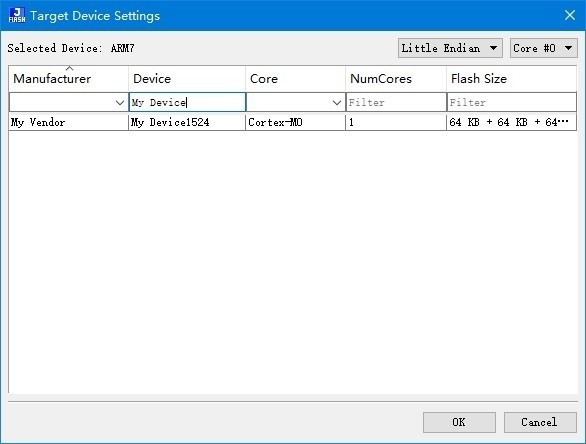
After double-clicking, you will enter the following interface.
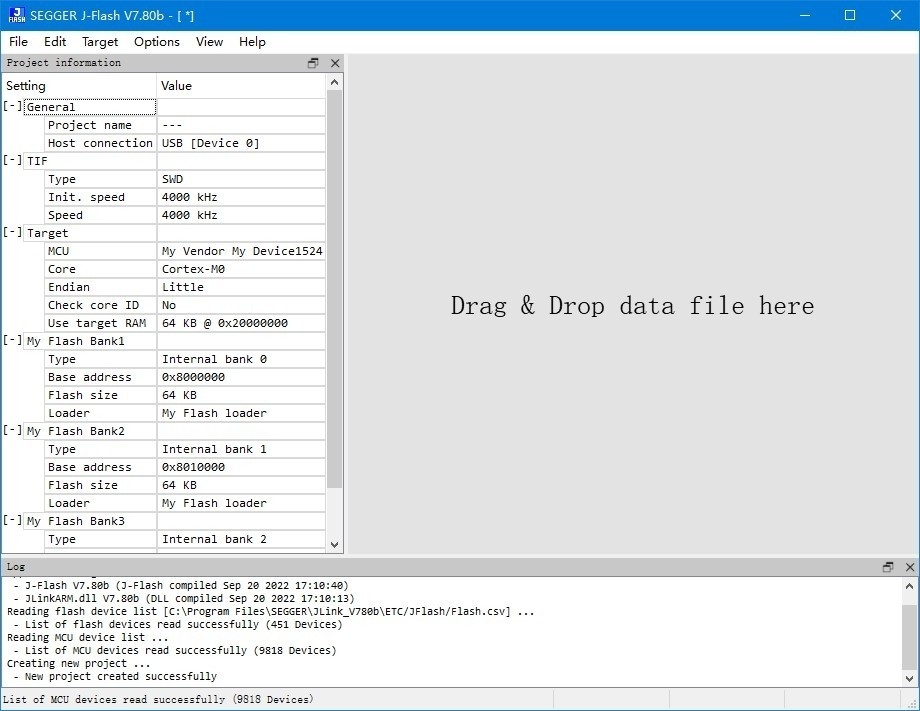
Now, our custom new device has been added. In a real project, you just need to modify the information according to the project’s device specifications.