The SDK implementation and register functionalities differ across MCU manufacturers. Misconfiguration due to unfamiliarity can lead to MCU instability.
This article will interpret the high-speed clock configuration and related considerations using the APM32E030’s user manual and SDK.
To understand the MCU’s high-speed clock, one must first consult the user manual.
High-speed clock sources are divided into internal and external sources:
Internal Clock Source
Internal clocks include HSICLK (High-Speed Internal Clock signal) and LSICLK (Low-Speed Internal Clock signal).
The HSICLK signal is generated by an internal 8MHz RC oscillator.
The frequency of the RC oscillator varies between different chips, and can also drift with temperature and voltage changes on the same chip. The HSICLK frequency of each chip is factory-calibrated to within 1% accuracy (at 25°C, VDD = VDDA = 3.3V).
External Clock Source
External clock signals include HSECLK (High-Speed External Clock signal) and LSECLK (Low-Speed External Clock signal).
There are two types of external clock sources:
- External crystal/ceramic resonator (standard passive crystals)
- User external clock (an active oscillator or a clock signal provided by another chip)
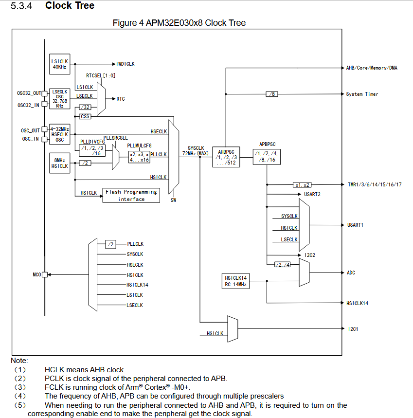
According to the E030 user manual, the maximum main frequency, SYSCLK, is 72MHz. The system clock source can be selected from HSECLK (external clock), PLLCLK (PLL clock), or HSICLK (internal 8MHz clock).
The input clock range for HSECLK is 4~ 32MHz. It can be configured to a maximum PLL frequency of 72MHz using the PLL’s prescaler and multiplier.
The HSICLK frequency is 8MHz. It must pass through a fixed divide-by-2 prescaler before entering the PLL multiplier. With a maximum multiplication factor of 16, the highest achievable main frequency is 64MHz.
The system clock is then routed to various peripherals after being configured through the AHBPSC and APBPSC prescalers. Special attention should be paid to the Timer (TMR) clock. The frequency for all TMRxCLK (timer clocks) is automatically set by hardware based on two conditions:
- If the corresponding APB prescaler is 1, the timer’s clock frequency is the same as the APB bus frequency.
- Otherwise, the timer’s clock frequency is set to twice the frequency of its connected APB bus.
The specific registers are detailed in the user manual, primarily the Clock Control Register 1 (RCM_CTRL1) and the Clock Configuration Register 1 (RCM_CFG1). Please refer to the user manual for their functions.
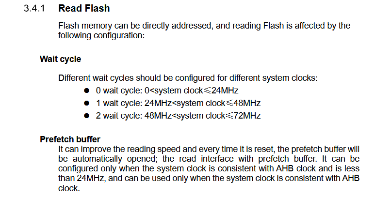
In addition to RCM-related registers, attention must be paid to the clock-related Flash wait states and prefetch buffer enable settings.
This covers the main theoretical aspects. For more details, it is recommended to review the user manual. Now, let’s move on to the code implementation.
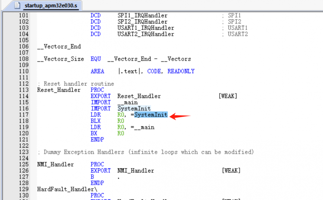
Upon power-on, the chip executes the startup file. After initializing the interrupt vector table, it enters the SystemInit() function for default clock initialization.
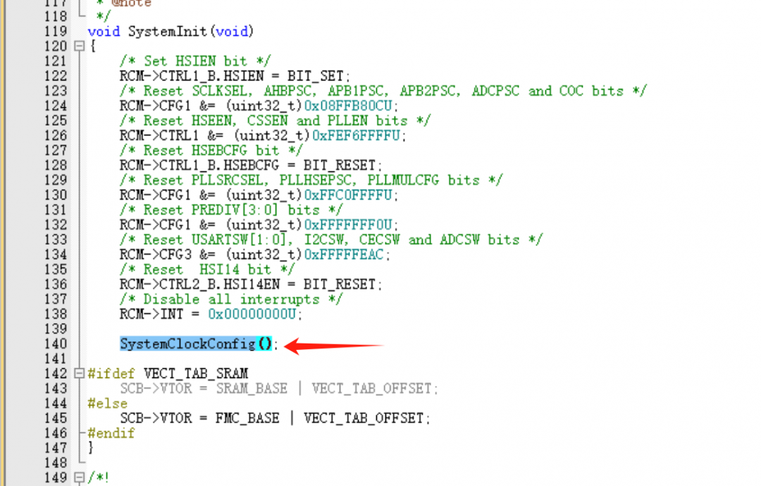
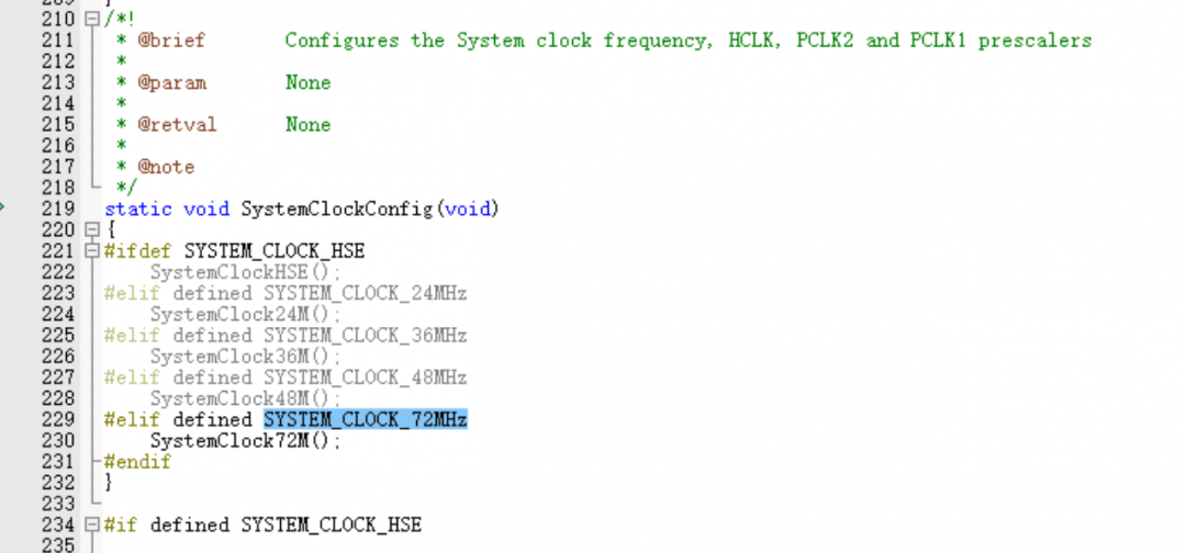
Within the SystemInit() function, clock-related registers are reset, and then SystemClockConfig() is called to perform the default clock initialization based on macro definitions.
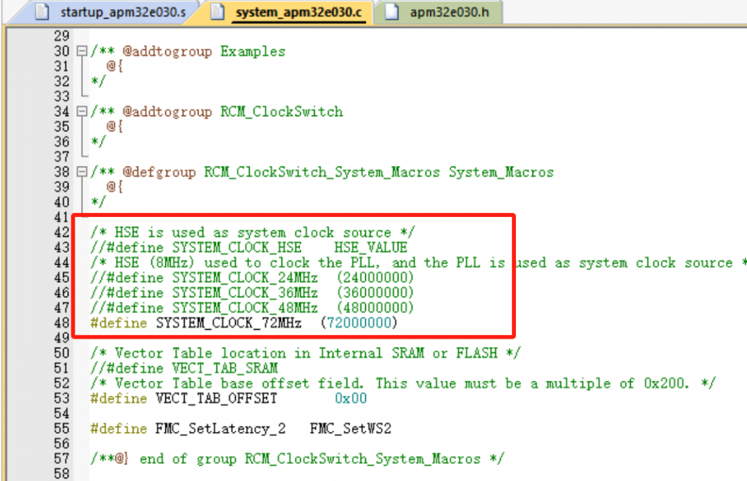
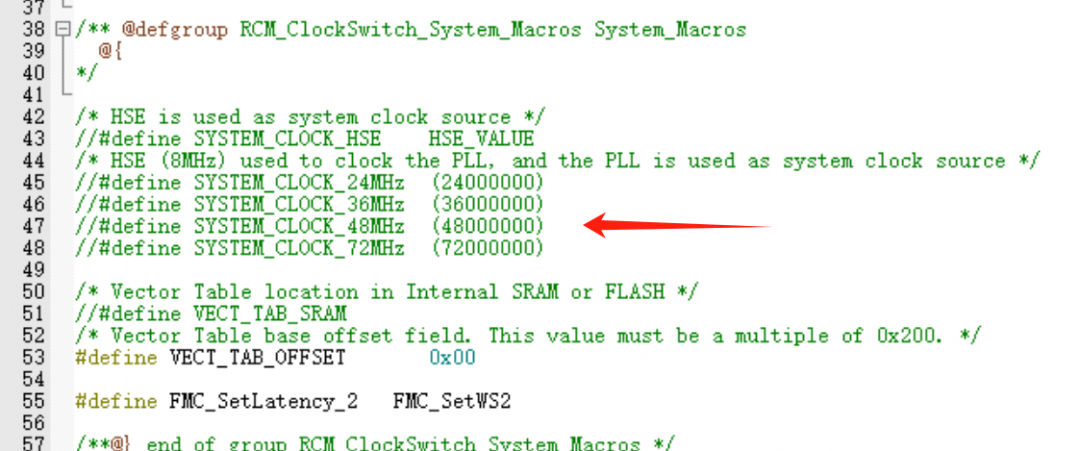
The SDK defaults to configuring a 72MHz main clock using an 8MHz external passive crystal.
If a lower main frequency is required, you can switch directly by selecting different macro definitions.
If an external high-speed crystal of a different frequency (e.g., 4MHz, 12MHz, 16MHz) is used, you cannot simply change the macro. The following modifications are necessary:
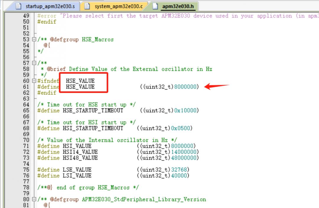
- Change HSE_VALUE to the actual crystal frequency. For example, if using a 12MHz crystal, modify it to:
#define HSE_VALUE ((uint32_t)12000000)
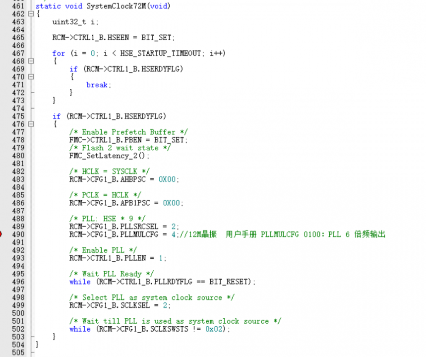
- Modify the PLL multiplication factor register. For a 12MHz crystal to achieve 72MHz, you need a 6x multiplier. Set PLLMULCFG=4, which corresponds to a 6x multiplier according to the datasheet (12MHz * 6 = 72MHz).
If the application does not require high clock precision and you want to use the internal oscillator (without an external crystal) to reach 64MHz, follow these steps:
Disable the macro definition that uses the external crystal.
Write the following clock initialization function for the internal oscillator and call it in your main function.
void SystemClock_HSI_PLL_Init()
{
RCM_Reset();
/* Enable HSI */
RCM_EnableHSI();
/* Wait until HSI is ready */
while (RCM->CTRL1_B.HSIRDY == RESET);
FMC_EnablePrefetchBuffer();
FMC_SetWS(FMC_WAIT_STATE_2); // FMC_SetWS2() in original article
RCM_ConfigAHB(RCM_SYSCLK_DIV_1);
RCM_ConfigAPB1(RCM_HCLK_DIV_1); // RCM_ConfigAPB in original article
/* SYSCLKFreq = (HSI * 16) / 2 */
RCM_ConfigPLL(RCM_PLL_SEL_HSI_DIV2, RCM_PLLMF_16);
/* Enable PLL */
RCM_EnablePLL();
while (RCM->CTRL1_B.PLLRDY == BIT_RESET);
/* Select PLL as Sysclk */
RCM_ConfigSYSCLK(RCM_SYSCLK_SEL_PLL);
while (RCM->CFG1_B.SCLKSWSTS != 0x02);
}
To switch the main clock frequency during runtime, for example, from 72MHz (using an external crystal) to 36MHz:
void SystemClock_HSE_PLL_Switch() // Renamed for clarity
{
uint32_t i;
/* Select HSI as System Clock at first */
RCM_ConfigSYSCLK(RCM_SYSCLK_SEL_HSI);
/* Disable PLL */
RCM_DisablePLL();
/* Wait until PLL is unlocked */
while (RCM->CTRL1_B.PLLRDY == SET);
RCM_ConfigHSE(RCM_HSE_OPEN);
for (i = 0; i < HSE_STARTUP_TIMEOUT; i++)
{
if (RCM->CTRL1_B.HSERDY)
{
break;
}
}
if (RCM->CTRL1_B.HSERDY)
{
FMC_EnablePrefetchBuffer();
FMC_SetWS(FMC_WAIT_STATE_2); // FMC_SetWS2() in original article
RCM_ConfigAHB(RCM_SYSCLK_DIV_1);
RCM_ConfigAPB1(RCM_HCLK_DIV_1); // RCM_ConfigAPB in original article
/* Config PLL source and multiplication factor
For 36MHz from 8MHz HSE: SYSCLKFreq = (HSE * 9) / 2 */
RCM_ConfigPLL(RCM_PLL_SEL_HSE, RCM_PLLMF_9);
RCM_ConfigCLKDIV(RCM_CLK_DIV_2); // Add PLL output divider
/* Enable PLL */
RCM_EnablePLL();
while (RCM->CTRL1_B.PLLRDY == BIT_RESET);
/* Select PLL as Sysclk */
RCM_ConfigSYSCLK(RCM_SYSCLK_SEL_PLL);
while (RCM->CFG1_B.SCLKSWSTS != 0x02);
}
else
{
/* Add handler for HSE startup failure */
}
}
To determine the current system clock configuration, you can refer to the RCM_ClockSwitch example in the SDK.
/* Initialize the USART */
APM_TINY_COMInit(COM1);
printf("sysSource = %s ", RCM_SYSCLK_SEL_TAB[RCM_ReadSYSCLKSource()]);
printf("sysClock = %" PRId32 "\r\n", RCM_ReadSYSCLKFreq());
Use the serial port to print the current clock configuration. Note that this printout is accurate only if the HSE_VALUE macro matches the actual crystal frequency. Be sure to verify it.
int main(void)
{
APM_TINY_LEDInit(LED2);
APM_TINY_LEDInit(LED3);
APM_TINY_PBInit(BUTTON_KEY1, BUTTON_MODE_EINT);
APM_TINY_PBInit(BUTTON_KEY2, BUTTON_MODE_EINT);
APM_TINY_COMInit(COM1);
ClockOutputInit();
printf("sysSource = %s ", RCM_SYSCLK_SEL_TAB[RCM_ReadSYSCLKSource()]);
printf("sysClock = %" PRId32 "\r\n", RCM_ReadSYSCLKFreq());
SystemClock_HSE_PLL_Init(); // Assuming this sets up the initial clock
for (;;)
{
Delay();
APM_TINY_LEDToggle(LED2);
}
}
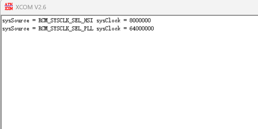
This is the test result when the startup file does not initialize the clock, and a 64MHz main clock is configured in main().