Foreword
If you’re new to Ethernet, especially when developing network applications with the APM32F407 MCU, you might find yourself bewildered by something called a “PHY.” It’s mentioned in documentation, configured in code, and required in hardware schematics. But what exactly is it? And why is it an indispensable part of any Ethernet communication discussion?
1. Introduction: What is a PHY and Why is It So Important?
Let’s use an analogy. Imagine Ethernet communication as a city-wide courier system. Your application’s data (like a UDP packet) is the “package,” the APM32F407 MCU is the “logistics center,” and the Ethernet cable is the “highway.” For a package to get from the logistics center to the customer, it must undergo a series of processes: packing, transport, and delivery. In this scenario, the PHY (Physical Layer) is like the “driver” responsible for loading the package from the digital world (of 0s and 1s) onto a truck and delivering it via the highway.
In the APM32F407’s Ethernet module, the PHY is the critical component that bridges digital signals with the physical world (cables, optical fibers, etc.). Without a PHY, data can neither be sent out over the cable nor received from it. Simply put, the PHY is the core component that makes Ethernet communication a physical reality, responsible for converting digital signals into electrical (or optical) signals and vice versa.
But what does a PHY actually do? How does it cooperate with the APM32F407’s Ethernet module? And why can its configuration be so complex?
2. Defining the PHY: What Exactly Is It?
PHY is the abbreviation for Physical Layer. In the OSI model (a seven-layer network model), the Physical Layer is the lowest layer, responsible for handling signal transmission related to the physical medium (like Ethernet cables or optical fibers). The PHY typically takes the form of a standalone chip (e.g., LAN8720, DP83825) or is integrated within more advanced SoCs.
In simple terms, a PHY is a “translator”:
- When transmitting: It translates the APM32F407’s digital signals (0s and 1s) into electrical signals that the Ethernet cable can understand.
- When receiving: It translates the electrical signals from the cable back into digital signals for the APM32F407 to process.
The PHY’s job is somewhat like the “converter” between your home router and the Ethernet cable. Without it, the digital and physical worlds cannot communicate.
2.1 PHY and MAC: A Perfect Pair
In Ethernet communication, the PHY is always found alongside another component—the MAC (Media Access Control). The MAC and PHY are like a dynamic duo, each with distinct responsibilities:
- MAC: Belongs to the Data Link Layer and is responsible for “packing” and “unpacking” data. It adds addresses and checksums to data to create a standard Ethernet frame, or it disassembles a received frame to pass the data to upper layers. The APM32F407’s Ethernet module has a built-in MAC.
- PHY: Belongs to the Physical Layer and is responsible for “transportation”. It converts the MAC’s packaged data into physical signals for the cable, or it converts signals from the cable back into digital data for the MAC.
You could say the MAC is the “packer” at the courier company, boxing up goods (data) and applying labels, while the PHY is the “driver” who transports the boxes to their destination.
[Figure 1: MAC and PHY Cooperation]
3. The Role of the PHY: What Does It Do?
To truly understand the PHY, we need to look at its specific roles in Ethernet communication. The PHY’s job can be broken down into three main areas: Signal Conversion, Link Management, and Interface Communication.
3.1 Signal Conversion: The Magic from Digital to Physical
The core task of the PHY is to convert between digital and physical signals. This might sound simple, but it’s a complex process involving encoding, modulation, and physical transmission.
- Transmission Process:
- The APM32F407’s MAC sends data (a stream of 0s and 1s) to the PHY via an interface (e.g., MII or RMII).
- The PHY encodes these 0s and 1s into a signal suitable for cable transmission. For example, in 100Mbps Ethernet, the PHY uses 4B/5B encoding (encoding 4 data bits into a 5-bit symbol) and MLT-3 modulation (Multi-Level Transmit-3) to convert the data into electrical signals.
- These electrical signals are sent out through the RJ45 connector and cable.
- Reception Process:
- The PHY receives electrical signals (which may be weak and noisy) from the cable.
- The PHY decodes the signal (e.g., demodulating MLT-3 and decoding 4B/5B) to recover the original 0s and 1s.
- The recovered digital data is sent back to the MAC via the MII/RMII interface.
In essence, the PHY acts as a “signal translator,” converting the MAC’s “Morse code” into the “electric waves” of the cable, and then translating those waves back into Morse code.
3.2 Link Management: Keeping the “Highway” Clear
The PHY not only handles signal conversion but also ensures the Ethernet “highway” is clear and operational. This includes:
- Auto-Negotiation: The PHY “talks” to the device at the other end (like a router) to agree on the communication speed (10Mbps or 100Mbps) and duplex mode (full-duplex or half-duplex).
- Link Detection: The PHY checks if the cable is properly connected and the link is active. If the cable is disconnected, the PHY will inform the MAC, “The road is out, stop sending data.”
- Error Detection: The PHY can detect errors in the signal (e.g., from noise interference) and notify the MAC via specific signals (like RX_ER).
Overall, the PHY is like the “traffic police” of the highway, not only transporting goods but also checking road conditions and coordinating traffic rules.
3.3 Interface Communication: “Talking” with the MAC
The PHY communicates with the MAC through standard interfaces like MII and RMII, which define the rules for data and control signal transmission. Common interfaces include:
- MII (Media-Independent Interface): Uses 18 signal lines, a 4-bit data width, and a 2.5/25MHz clock.
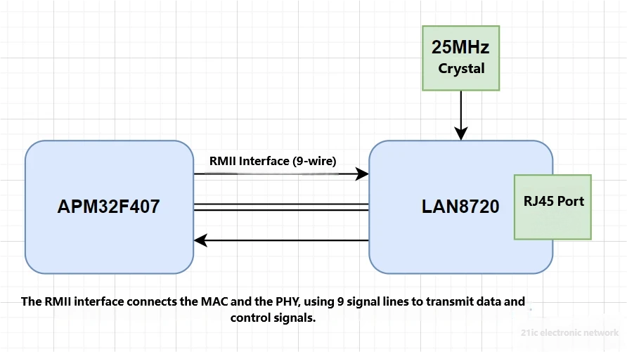
- RMII (Reduced Media-Independent Interface): Uses 9 signal lines, a 2-bit data width, and a 50MHz clock.
The PHY uses these interfaces to receive data from the MAC, send its own data, or accept configuration commands from the MAC via the management interface (MDC/MDIO). In short, MII/RMII are like the “telephone lines” between the MAC and PHY, used to pass along packages and instructions.
4. How the PHY Works: How Does Data Move?
Now that we know the PHY is a “translator + traffic cop,” how does it actually work? Let’s take the APM32F407 and a common PHY chip (like the LAN8720 with an RMII interface) as an example to dissect the PHY’s operating principle.
4.1 Internal Structure of a PHY
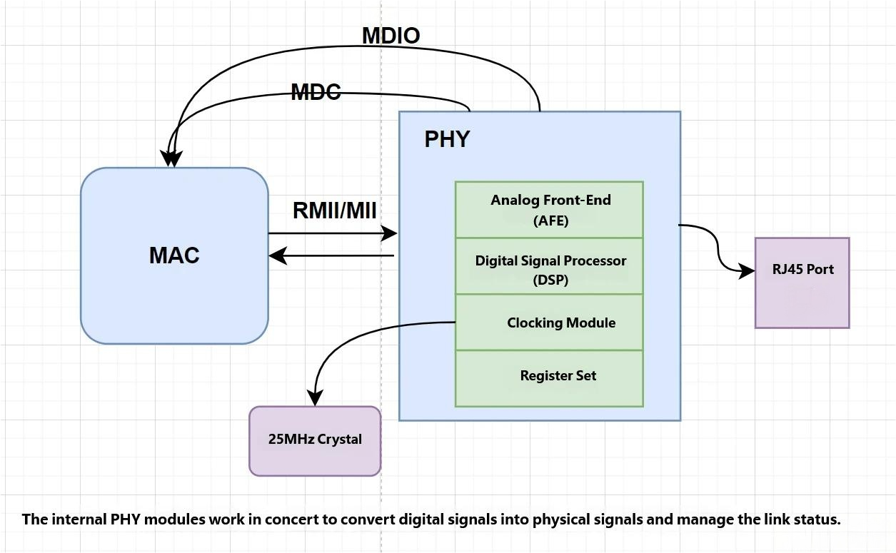
A PHY chip is like a small factory containing several key modules:
- Analog Front-End (AFE): Responsible for converting digital signals into analog electrical signals and vice versa. The AFE interfaces directly with the Ethernet cable.
- Digital Signal Processor (DSP): Handles encoding, decoding, and error correction to ensure signal reliability.
- Clock Module: Generates or receives clock signals (like the 50MHz REF_CLK for RMII) to synchronize data transfer.
- Register Set: Stores the PHY’s configuration (like speed and duplex mode) and status (like link status).
- Interface Module: Communicates with the MAC via MII/RMII and accepts configuration via MDC/MDIO.
[Figure 2: PHY Internal Structure]

4.2 The Data Transmission Process
Suppose we want to send a UDP packet using the APM32F407. How does the PHY get the data onto the wire?
- MAC Prepares Data:
- Your application generates a UDP packet (e.g., “Hello, World!”).
- The APM32F407’s MAC adds an Ethernet frame header (destination address, source address, etc.) and a checksum to create a complete data frame.
- The MAC sends the data to the PHY via the RMII interface (using LAN8720 as an example).
- PHY Receives Data:
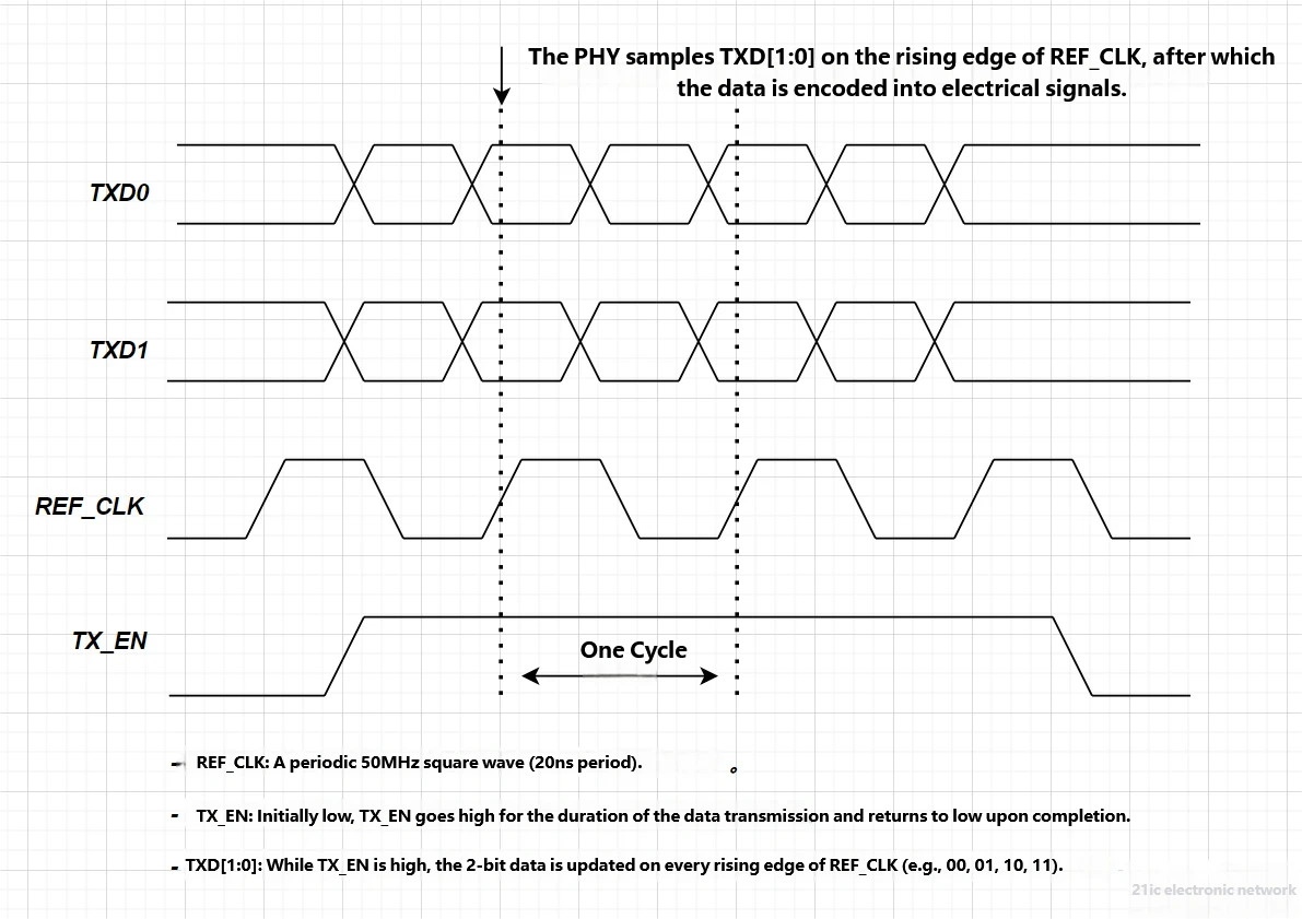
- The MAC sends the data in 2-bit groups over TXD[1:0] to the LAN8720.
- The MAC also asserts TX_EN high to tell the PHY, “Data is coming.”
- The LAN8720 samples the data on TXD[1:0] on the rising edge of the 50MHz REF_CLK.
- PHY Encodes and Modulates:
- The LAN8720’s DSP encodes the 2-bit data into 5-bit symbols (4B/5B encoding), adding redundancy for reliability.
- The AFE modulates the encoded data into an MLT-3 signal (a three-level electrical signal) suitable for cable transmission.
- Signal Transmission:
- The modulated electrical signal is sent through the RJ45 connector and cable to the peer device (e.g., a router).
[Figure 3: PHY Transmission Timing (RMII)]
4.3 The Data Reception Process
Now for the reverse: a router sends a packet. How does the PHY receive it?
- PHY Receives Signal:
- The LAN8720 receives an electrical signal (in MLT-3 format) from the cable via the RJ45 connector.
- The AFE amplifies the signal, removes noise, and demodulates it back into digital symbols.
- PHY Decodes:
- The DSP decodes the symbols (5B/4B decoding) to recover the 2-bit data.
- If an error is detected (e.g., signal distortion), the PHY notifies the MAC via the RX_ER signal.
- PHY Sends Data to MAC:
- The LAN8720 places the 2-bit data onto RXD[1:0].
- It asserts CRS_DV high to tell the MAC, “Data is available.”
- The MAC samples the data on RXD[1:0] on the rising edge of REF_CLK.
- MAC Processing:
- The APM32F407’s MAC reassembles the data into a complete frame and passes it to the upper-layer software (like the LwIP stack) for processing.
[Figure 4: PHY Reception Timing (RMII)]
4.4 Link Management and Auto-Negotiation
The PHY also “talks” with the peer device to ensure smooth communication. For example:
- Auto-Negotiation: The LAN8720 sends special pulse signals (Fast Link Pulses) to negotiate the speed and duplex mode with the peer. The result is stored in the PHY’s registers, which the MAC can read via MDC/MDIO.
- Link Status: The PHY continuously monitors the cable connection. If the cable is unplugged, the PHY updates its status register to notify the MAC.
You can think of the PHY as a “diplomat” that, while transporting goods, also negotiates terms with the other side to ensure both parties use the same “language” and “speed.”
5. Using the PHY with APM32F407: How to Do It?
In APM32F407 Ethernet development, the PHY is typically an external chip (like LAN8720 or DP83825) connected to the built-in MAC via the MII or RMII interface. Below is the typical workflow for using a PHY in development. Geehy’s official SDK also provides ETH examples that you can reference.
5.1 Hardware Connection
Taking the LAN8720 (RMII interface) as an example, the connection to the APM32F407 is as follows (pinouts may vary by board):
| Signal Name | APM32F407 Pin | LAN8720 Pin | Function |
|---|
| TXD0 | PB12 | TXD0 | Transmit Data Bit 0 |
| TXD1 | PB13 | TXD1 | Transmit Data Bit 1 |
| TX_EN | PB11 | TX_EN | Transmit Enable |
| RXD0 | PC4 | RXD0 | Receive Data Bit 0 |
| RXD1 | PC5 | RXD1 | Receive Data Bit 1 |
| CRS_DV | PA7 | CRS_DV | Carrier Sense/Data Valid |
| REF_CLK | PA1 | REF_CLK | 50MHz Reference Clock |
| MDC | PC1 | MDC | Management Clock |
| MDIO | PA2 | MDIO | Management Data |
Note:
- The LAN8720 requires a 25MHz crystal to provide its clock.
- The RJ45 connector needs an integrated transformer for signal isolation and impedance matching.
[Figure 5: APM32F407 and LAN8720 Connection]
5.2 Initializing the PHY
Before using the PHY, you need to initialize both the APM32F407’s MAC and the LAN8720. The steps are:
- Enable Clocks:
- Enable the clocks for the Ethernet MAC, GPIO, and DMA.
- Ensure the LAN8720’s power supply and crystal are active.
- Configure GPIO:
- Configure TXD[1:0], TX_EN, MDC, and MDIO as Alternate Function Push-Pull outputs.
- Configure RXD[1:0], CRS_DV, and REF_CLK as inputs (or outputs, depending on the REF_CLK source).
- Configure MAC:
- Set the interface to RMII mode, speed to 100Mbps, and duplex mode to Full-Duplex.
- Configure PHY:
- Write to the LAN8720’s control registers (e.g., address 0×00) via MDC/MDIO to set the speed and duplex mode.
- Read the status register (address 0×01) to confirm the link status.
Code Example: PHY Initialization
#include "apm32f4xx_eth.h"
#include "apm32f4xx_gpio.h"
#include "apm32f4xx_rcm.h"
void PHY_Init(void)
{
GPIO_Config_T gpioConfig;
ETH_Config_T ethConfig;
// Enable clocks
RCM_EnableAHB1PeriphClock(RCM_AHB1_PERIPH_ETHMAC | RCM_AHB1_PERIPH_ETHMACTX | RCM_AHB1_PERIPH_ETHMACRX);
RCM_EnableAPB2PeriphClock(RCM_APB2_PERIPH_GPIOA | RCM_APB2_PERIPH_GPIOB | RCM_APB2_PERIPH_GPIOC);
// Configure GPIO
gpioConfig.mode = GPIO_MODE_AF;
gpioConfig.speed = GPIO_SPEED_50MHz;
gpioConfig.outType = GPIO_OUT_TYPE_PP;
gpioConfig.pupd = GPIO_PUPD_NOPULL;
gpioConfig.pin = GPIO_PIN_1 | GPIO_PIN_2 | GPIO_PIN_7;
GPIO_Config(GPIOA, &gpioConfig);
gpioConfig.pin = GPIO_PIN_11 | GPIO_PIN_12 | GPIO_PIN_13;
GPIO_Config(GPIOB, &gpioConfig);
gpioConfig.pin = GPIO_PIN_4 | GPIO_PIN_5;
GPIO_Config(GPIOC, &gpioConfig);
GPIO_ConfigPinAF(GPIOA, GPIO_PIN_SOURCE_1, GPIO_AF_ETH); // REF_CLK
GPIO_ConfigPinAF(GPIOA, GPIO_PIN_SOURCE_2, GPIO_AF_ETH); // MDIO
// ... other alternate function configurations
// Configure MAC
ethConfig.mode = ETH_MODE_FULLDUPLEX;
ethConfig.speed = ETH_SPEED_100M;
ethConfig.interface = ETH_INTERFACE_RMII;
ETH_Config(ðConfig);
// Configure LAN8720
ETH_WritePHYRegister(0x00, 0x00, 0x3100); // 100Mbps, Full-duplex
ETH_Start();
}
5.3 Data Transmission and Reception
The data transfer process was detailed in Section 4. Here’s a summary:
- Transmission: The MAC sends data via TXD[1:0] and TX_EN; the PHY encodes it and sends it over the cable.
- Reception: The PHY decodes the signal from the cable and passes it to the MAC via RXD[1:0] and CRS_DV.
Code Example: Data Transmission/Reception
void ETH_SendPacket(uint8_t* data, uint32_t len)
{
ETH_TxDescriptor_T txDesc;
txDesc.buffer1Addr = (uint32_t)data;
txDesc.length = len;
DAL_ETH_Transmit(&txDesc);
}
void ETH_ReceivePacket(uint8_t* buffer, uint32_t* len)
{
ETH_RxDescriptor_T rxDesc;
if (DAL_ETH_Receive(&rxDesc) == DAL_OK)
{
*len = rxDesc.length;
memcpy(buffer, (uint8_t*)rxDesc.buffer1Addr, *len);
}
}
In summary, the PHY is responsible for signal conversion, link management, and interface communication, making Ethernet communication possible.
6. References
- APM32F407 User Manual
- LAN8720 Datasheet
- DP83825 Datasheet
- IEEE 802.3 Standard
- LwIP Protocol Stack Documentation