I am currently developing an IoT device that integrates an MCU with a wireless module. To strike a balance between a robust development ecosystem and strict cost control, I selected the Geehy APM32E030C8T6.
Manufactured on a 55nm process, this MCU offers an optimized design with:
- Basic communication peripherals, like 26Mbit/s USART and 2IIC supporting Fast Mode+.
- Advanced ADC functionality.
- Impressive power consumption and reliability figures.
🛠 The Challenge: Pin Scarcity
My product architecture involves controlling multiple sensor ICs and external memory, alongside managing 8 channels of ADC input. This extensive peripheral load left me with very few free GPIOs.
To solve this, I decided to utilize the USART2 peripheral on pins PA14 and PA15.
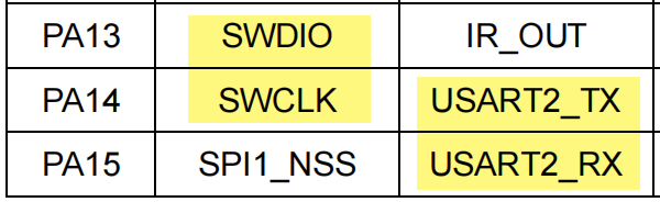
The pin PA14 is default to SWD_SWCLK functionality. By multiplexing the SWD clock pin for UART communication, I could save valuable GPIO resources for other tasks.
🐛 The Debugging Journey
Phase 1: SDK Exploration
I started by exploring the APM32E030_SDK. Two examples caught my eye:
- USART_Polling: A polling-based example using USART1 for debugging and USART2 send data to USART1, I can simply connect USART2_TX with USART1_RX to verify both modules.
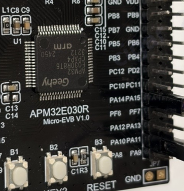
- USART_Interrupt: This example demonstrates interrupt-based TX/RX on USART1 and works seamlessly with the APM32E030_Micro-EVB (which features an onboard Geehy Link CMSIS-DAP Debugger).
Since I knew USART2 would eventually occupy the SWCLK pin (complicating debugging later), I decided to first encapsulate and test my communication logic using USART1 based on the USART_Interrupt example. Everything worked perfectly.
Phase 2: The “APB Clock” Trap
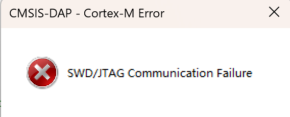
When I ported the code from USART1 to USART2, communication completely failed. No data was sent or received.
I scrutinized the datasheet and registers. USART1 and USART2 looked identical; both are connected to the APB bus. However, a deeper dive into the APB architecture revealed the root cause. The APM32E030 has two APB sets, requiring different initialization functions.
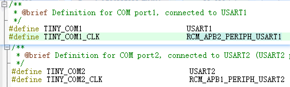
I updated the macro definitions from COM1 to COM2, but I ignored the bus architecture differences.
// My macro definition
#define TINY_COM2_CLK RCM_APB1_PERIPH_USART2
// The WRONG function call I used (APB2 instead of APB1)
RCM_EnableAPB2PeriphClock(TINY_COM2_CLK);
Because I used RCM_EnableAPB2PeriphClock with the USART2 macro value, I accidentally enabled the clock for Timer 15 (which shares the same bit position on APB2) instead of USART2.
The Fix:
Changing the function call to RCM_EnableAPB1PeriphClock(...) immediately fixed the transmitter (TX).
Phase 3: The Silent Crash (Interrupt Handler)
With the clock fixed, I could send messages via USART2. However, the moment the MCU received a byte, it stopped working entirely. This was baffling.
I went back to the SDK structure and checked apm32e030_int.c, the file that houses the Interrupt Service Routines (ISRs). I realized that the example code only defined the handler for USART1.
According to the startup file, the handler is defined as [WEAK]:
EXPORT USART2_IRQHandler [WEAK]
The Fix:
I had to manually add the specific handler for USART2 in apm32e030_int.c. By simply changing one character from the USART1 function, the reception logic started working:
// Added to apm32e030_int.c
void USART2_IRQHandler(void)
{
USART_Receive_Isr();
}
📝 Summary
Developing with the APM32E030 has been a rewarding journey. The key takeaways from this experience are:
- Check your APB Bridges: Always verify if a peripheral is on APB1 or APB2 and use the corresponding
RCM function.
- Verify ISRs: When porting code, ensure the
_int.c file contains the interrupt handler for the specific peripheral instance (e.g., USART2 vs USART1).
- Pin Multiplexing: Don’t be afraid to reuse SWD pins if you manage the reset sequence correctly.