In embedded system design, power management is a critical topic. For devices based on APM32 (Microcontroller Units), minimizing power consumption while maintaining functionality is a key design challenge. APM32 MCUs typically offer several low-power modes, with Stop Mode and Standby Mode being the most common. Both modes can significantly reduce power consumption, but they differ markedly in their operating principles, peripheral states, data retention methods, and wake-up behaviors.
This article will address the following questions:
- What are the core principles for entering and exiting low-power modes?
- In Stop mode, are all peripherals stopped? Which ones can still run, and why?
- Is the CPU stopped in Standby mode? How does data retention differ before entering Stop and Standby modes, and why?
- Are the entry mechanisms and principles for these two modes different?
- Why can the MCU resume execution after waking from Stop mode, but must restart from the beginning after waking from Standby mode?
- In Stop mode, both HSE/HSI are off. How can an external GPIO interrupt be triggered? With the clocks off, how can an interrupt even be generated?
By providing a detailed analysis of these questions, this article aims to help you comprehensively understand the core logic of APM32 MCU low-power design, moving you from “knowing how to use it” to “truly understanding it,” and from “copying example code” to “independently optimizing” your designs.
#### 1. Basic Principles of APM32 MCU Low-Power Modes
1.1 The Core Idea of Low-Power Modes: Dynamic Power = Switching Activity × Frequency × Voltage²
The power consumption of an MCU primarily comes from clock-driven circuit activity, including:
- CPU instruction execution (each instruction → register toggling)
- Peripheral clocks (UART, SPI, ADC, etc.)
- Bus activity (AHB/APB bridges)
- Analog modules (PLL, LDO)
You can think of it this way:
A chip is like a large factory, and the clock is the work bell. When the bell rings, all workers (circuits) start their tasks, flipping switches → consuming power. Turning off the bell = turning off the clock = massive power savings.
The core method to reduce power consumption is to turn off or lower the clock frequency, reducing circuit switching and thereby lowering dynamic power (P = C × V² × f).
Low-power modes achieve energy savings through the following means:
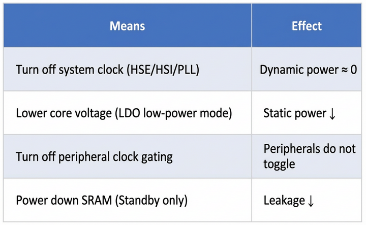
Different modes represent different trade-offs between power consumption and functional retention—a classic “can’t have your cake and eat it too” scenario.
1.2 Core Principles of Entering and Exiting Low-Power Modes (WFI/WFE** + SLEEPDEEP + PMU Handshake)**
In a nutshell:
WFI is the “Pause button,” SLEEPDEEP is the “Deep Sleep switch,” and the PMU is the “Executor”—these three work together to decide whether to “pause the movie” or “shut down and restart.”
1.2.1 Entering Low-Power Mode (Assembly-Level + Hardware Handshake)
- Software Configuration
PMU->CTRL1.PDDSCFG = 1; // Standby: Power down; 0: Stop clocks only
SCB->SCR.SLEEPDEEP = 1; // Inform the core it can enter Deep Sleep
- Trigger Instruction (ARM Cortex-M Assembly Behavior)
WFI ; 0xBF20 → Wait For Interrupt, pause instruction fetching
; or
WFE ; 0xBF22 → Wait For Event (controlled by SEVONPEND)
- WFI: The CPU stops fetching instructions, but the PC pointer is maintained.
- WFE: Supports event-based wake-up, often used for multi-core synchronization.
- Core Response
SLEEPDEEP=1 → The core notifies the PMU: you are authorized to shut down clocks/power.- PMU Execution:
- Stop: Turns off HSE/HSI/PLL, SRAM is retained.
- Standby: Turns off the LDO, SRAM is powered down.
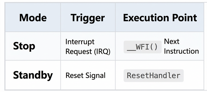
1.2.2 Exiting Low-Power Mode (Interrupt vs. Reset Path)

Key Difference:
- Stop: Program flow is uninterrupted, variables are retained.
- Standby: The system restarts, requiring re-initialization.
One-sentence summary:
WFI pauses the CPU, SLEEPDEEP authorizes the PMU, and PDDSCFG decides whether to cut power—all three are essential.
#### 2. Stop Mode In-Depth
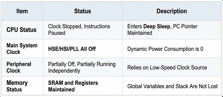
2.1 CPU and Peripheral Status in Stop Mode
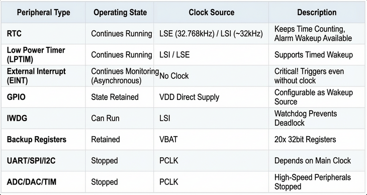
2.2 Which Peripherals Can Continue to Run? (Detailed Table)
2.3 Why Can Peripherals Run When the CPU is Stopped? (Three-Domain Architecture)
A chip is not a monolithic block but is divided into three distinct domains:
- CPU Domain: Relies on the main clock; goes to sleep when it’s off.
- RTC Domain: Has its own “small generator” (LSE/LSI), independent of the main power grid.
- GPIO Domain: Directly connected to the power supply (VDD); a button press gets an immediate response!
Figure 1: APM32 Low-Power Three-Domain Architecture Diagram
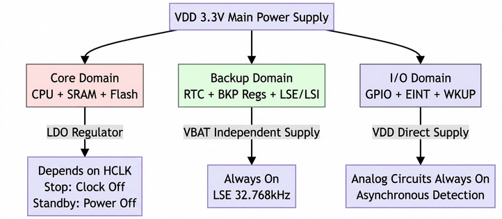
- Core Domain: Depends on HCLK; the clock is gated in Stop mode.
- Backup Domain: Has an independent clock source and is always powered.
- I/O Domain: Directly supplied by VDD; its analog circuitry is always on.
2.4 How Can GPIO External Interrupts Trigger When HSE/HSI are Off in Stop Mode?
User’s Question:
“If all the clocks are off, how does EINT know the pin level has changed? How can this thing work without a clock?”
4.1 Analogy: A Doorbell Can Ring Without Relying on the Main Power Meter
Imagine your doorbell:
- Button = GPIO Pin
- Bell Ringing = EINT Interrupt
When you go to sleep, you turn off all the lights in your house (HSE/HSI), but the doorbell circuit is wired directly to a battery!
When someone presses the button → the bell rings. It doesn’t need to wait for the power meter to spin (PCLK sampling)!
EINT is exactly this “doorbell circuit wired directly to a battery.” It doesn’t rely on the CPU clock but works using analog circuitry + asynchronous triggers.
4.2 Complete Breakdown of the EINT Asynchronous Wake-up Path
4.2.1 Hardware Components (Reference: APM32F407 RM, Section 12.3)
Figure 2: EINT Asynchronous Wake-up Path (Clockless Trigger Principle)
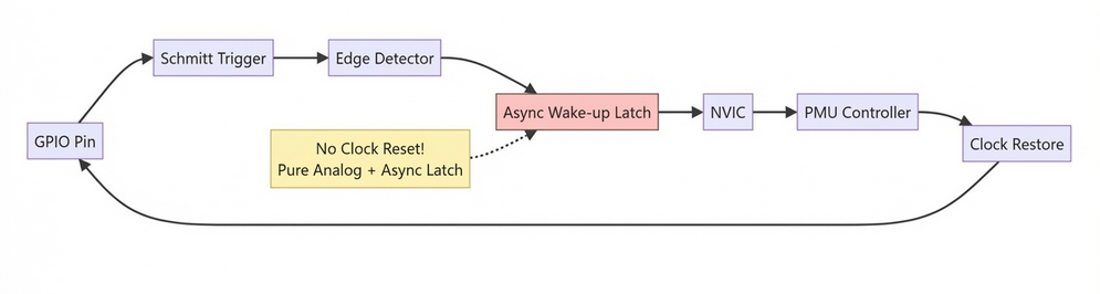
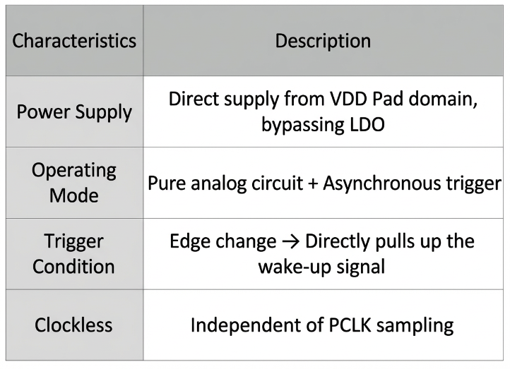
4.2.2 Key Module: The Always-On Analog Front-End
4.2.3 Code Example: Waking from Stop Mode with a Push-Button
void Enter_Stop_With_EINT(void)
{
// 1. Configure PA0 as an external interrupt (rising edge)
EINT->RTEN |= EINT_RTEN_RTEN0; // Enable rising edge trigger
EINT->IMASK |= EINT_IMASK_IMASK0; // Enable interrupt line 0
// 2. Enable PMU clock
RCM->APB1CLKEN |= RCM_APB1CLKEN_PMUEN;
// 3. Enter Stop mode
PMU->CTRL1 &= ~PMU_CTRL1_PDDSCFG; // Clear PDDSCFG -> Selects Stop mode
SCB->SCR |= SCB_SCR_SLEEPDEEP_Msk;
__WFI(); // CPU pauses, HSE/HSI are turned off
}
// EINT0 Interrupt Service Routine
void EINT0_IRQHandler(void)
{
if (EINT->SWINTE & EINT_SWINTE_SWINT0)
{
EINT->IPEND = EINT_IPEND_IPEND0; // Clear the flag
// CPU has resumed, execution continues from the instruction after __WFI()
}
}
Button press → Asynchronous edge detection → Wakes up the CPU → Program flow is uninterrupted.
2.5 Stop Mode Wake-up Mechanism (Full Process)
- Wake-up Sources: RTC Alarm, LPTIM, EINT, USART RX, etc.
- Signal Path:
- Peripheral → Generates an interrupt request.
- NVIC → Detects the interrupt while
SLEEPDEEP=1.
- Triggers the clock restoration sequence.
- Restoration Sequence:
- HSE/HSI starts up → PLL locks → HCLK is restored → CPU exits Sleep.
- Execution Point: Resumes from the instruction immediately following
__WFI().
#### 3. Standby Mode In-Depth
3.1 CPU and Peripheral Status in Standby Mode (Ultra-Detailed Status Matrix)
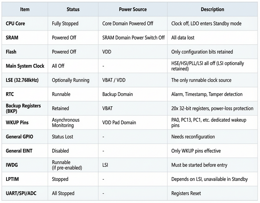
Key Difference:
Stop mode is like “pausing a movie,” while Standby is like “shutting down and restarting the computer”!
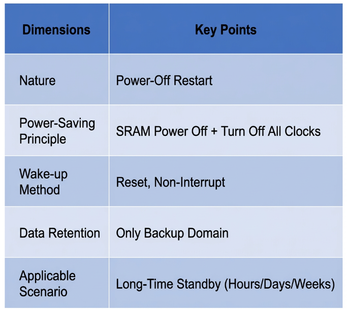
3.2 Why is Data Lost When Entering Standby Mode? (Silicon-Level Leakage Analysis)
2.1 SRAM is a Major Source of Leakage Current
Think of SRAM as rows of tiny capacitors:
- To store a
1, a capacitor is charged.
- Even when not being accessed, these capacitors slowly leak charge (on the order of nA).
- 100KB SRAM × 10nA/KB = 1μA of leakage current!
Standby mode “pulls the plug on SRAM’s power supply” → Leakage = 0 → Power consumption drops to as low as 3μA!
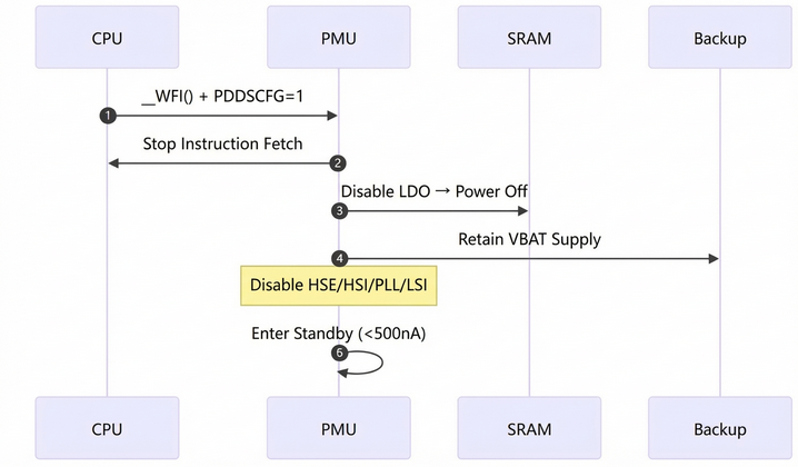
2.2 Power Domain Shutdown Sequence (Internal PMU Behavior)
Figure 3: Standby Mode Power Domain Shutdown Sequence Diagram
3.3 Standby Mode Wake-up Mechanism (Full Chain Breakdown)
3.1 List of Wake-up Sources
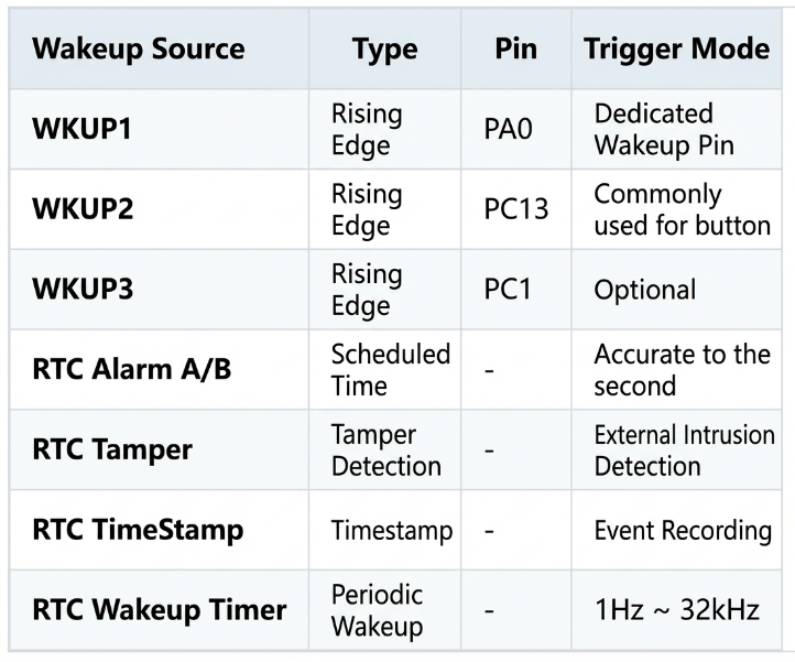
3.2 Asynchronous Detection Mechanism of WKUP Pins (and the difference from EINT!)
- Normal EINT: Usable in Stop mode, on any GPIO.
- WKUP Pins: Dedicated for Standby mode, on fixed pins.
Hardware Principle (Similar to EINT, but more “hard-wired”):
Figure 4: WKUP Pin vs. Normal EINT Wake-up Path Comparison
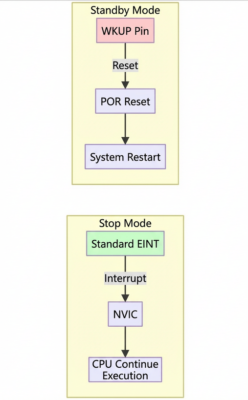
Key Difference:
- EINT → Triggers an interrupt → CPU continues execution.
- WKUP → Triggers a reset → System restarts.
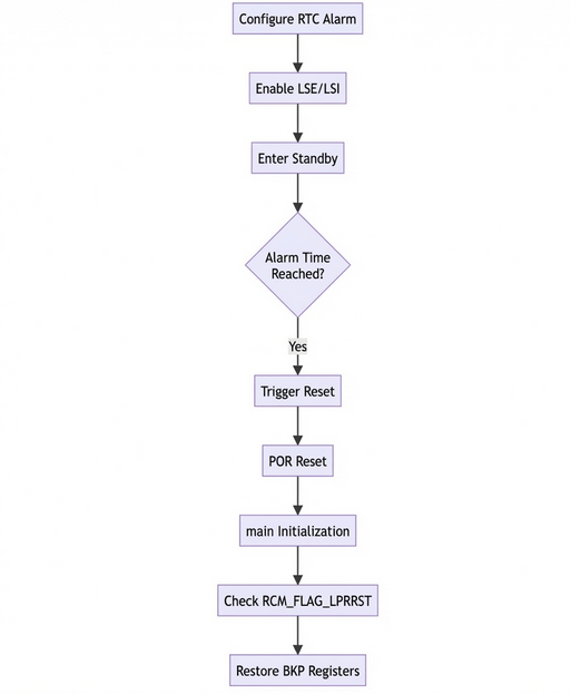
3.3 Code Example: Waking from Standby with RTC Alarm
void Enter_Standby_With_RTC_Alarm(void)
{
// 1. Enable RTC clock
RCM->APB1CLKEN |= RCM_APB1CLKEN_PMUEN;
PMU->CTRL1 |= PMU_CTRL1_BPWEN;
RCM_EnableLSI();
/* Wait till LSI is ready */
while(RCM_ReadStatusFlag(RCM_FLAG_LSIRDY) == RESET) {}
/* Select the RTC Clock Source */
RCM_ConfigRTCCLK(RCM_RTCCLK_LSI);
RCM->BDCTRL |= RCM_BDCTRL_RTCCLKEN;
// 2. Configure RTC Alarm
RTC->CTRL &= ~RTC_CTRL_ALRAEN; // Disable alarm write protection
while(!(RTC->STS & RTC_STS_ALRAWF)); // Wait until write is allowed
RTC->ALRMAR = 0x00800000; // Set alarm time
RTC->CTRL |= RTC_CTRL_ALRAEN | RTC_CTRL_ALRAIEN; // Enable Alarm A + Interrupt
// 3. Enter Standby mode
PMU->CTRL1 |= PMU_CTRL1_PDDSCFG;
SCB->SCR |= SCB_SCR_SLEEPDEEP_Msk;
__WFI();
}
// After RTC wake-up: System resets and enters main()
int main(void)
{
if (RCM_ReadStatusFlag(RCM_FLAG_LPRRST)) // Check if it was a Standby wake-up
{
// Restore state from backup registers
uint32_t state = RTC->BKP0R;
}
SystemClock_Config(); // Must re-initialize the clock!
GPIO_Init();
// ...
}
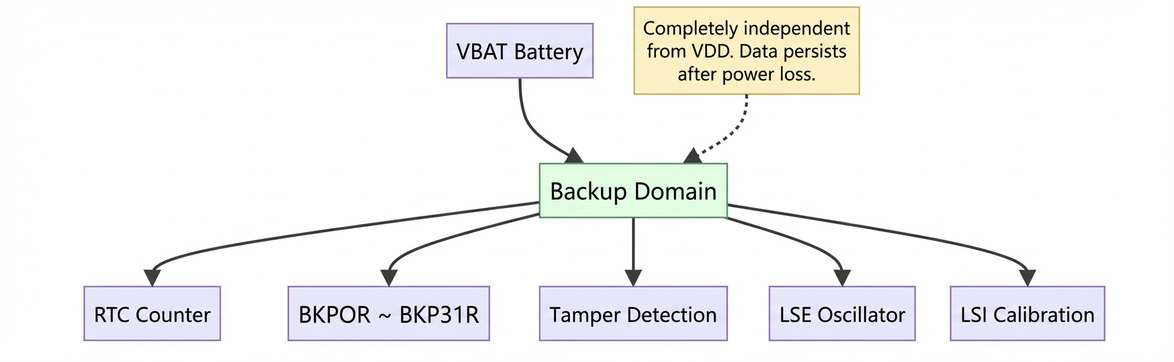
3.4 A Complete View of the Backup Domain
4.1 Architecture Diagram
Figure 5: Backup Domain Architecture
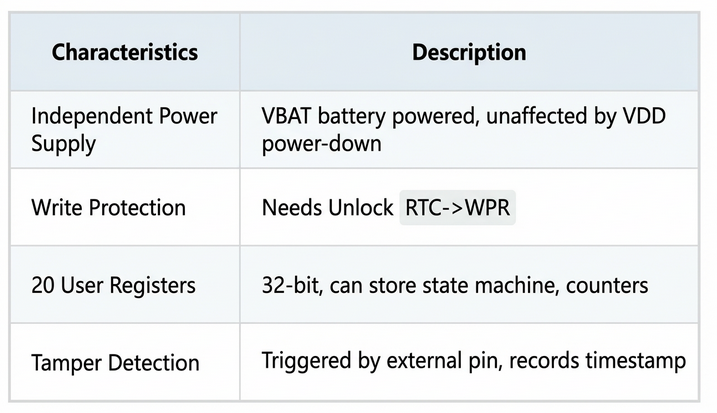
4.2 Key Features
4.3 Saving State Before Sleep Using Backup Registers
// Before entering Standby
RTC->BKP0R = system_state;
RTC->BKP1R = error_code;
// After wake-up (in main())
if (RCM_ReadStatusFlag(RCM_FLAG_LPRRST))
{
system_state = RTC->BKP0R;
error_code = RTC->BKP1R;
}
3.5 Full Process of System Reset After Standby Wake-up (Hardware to Software)
Figure 6: Complete Flowchart for RTC Alarm Wake-up from Standby
3.6 Summary: Core Logic of Standby Mode
Remember this one-liner:
Standby = “Shut down to save power, restart to get work done.”
#### 4. Stop vs. Standby Mode Comparison (Extended Table)
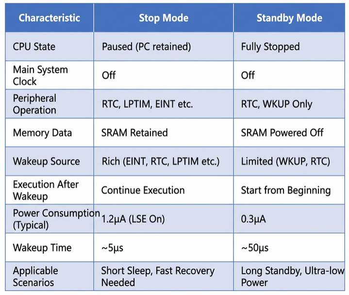
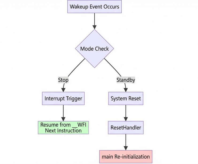
Figure 7: Stop vs. Standby Post-Wake-up Execution Flow
#### 5. Differences in Entry and Exit Mechanisms
5.1 Entry Mechanism
Stop Mode (Code)
PMU->CTRL1 &= ~PMU_CTRL1_PDDSCFG; // Clear PDDS bit -> Stop
SCB->SCR |= SCB_SCR_SLEEPDEEP_Msk;
__WFI();
Standby Mode (Code)
PMU->CTRL1 |= PMU_CTRL1_PDDSCFG; // Set PDDS bit -> Standby
PMU->CSTS |= PMU_CSTS_WKUPCFG; // Enable WKUP
SCB->SCR |= SCB_SCR_SLEEPDEEP_Msk;
__WFI();
Figure 8: Register Configuration Flow for Entering Stop/Standby
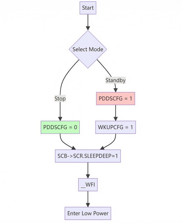
Key Difference:
The PDDS bit determines whether to power down the SRAM.
5.2 Exit Mechanism
#### 6. Conclusion
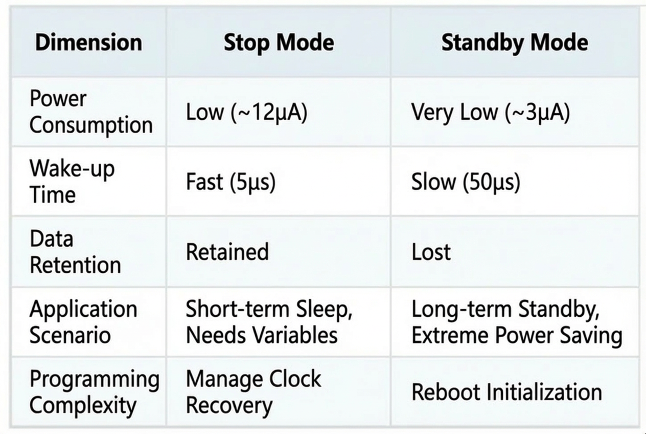
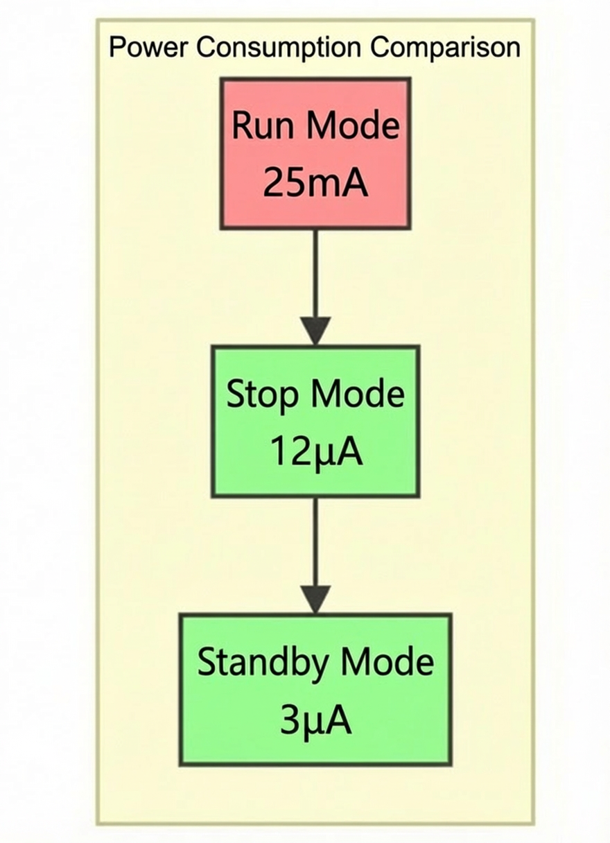
Figure 9: Low-Power Mode Power Consumption Bar Chart (Illustrative)
Understanding the core principles and peripheral states of APM32 MCU low-power modes is crucial for designing efficient, energy-saving embedded systems.
- Stop Mode: Ideal for fast wake-up + data retention.
- Standby Mode: Perfect for ultra-low power + long-term standby.
The most challenging concept—the “clockless interrupt”—is actually a feat of hardware analog circuitry:
The edge detection of EINT is asynchronous, implemented with Schmitt triggers and latches, and requires no clock whatsoever!