In the world of embedded development, motor control is widely regarded as one of the most challenging yet rewarding domains. A stable and efficient Sensorless FOC (Field Oriented Control) driver is not just a collection of code; it is a modern masterpiece of real-time performance, mathematical algorithms, and hardware resource optimization.
Today, we will use a typical project based on the G32 Series Motor Dedicated Cortex-M0+ MCU & SoC product line as an example to deconstruct what constitutes a professional motor driver.
Whether you are a beginner or a veteran looking for architectural optimization, this guide will provide you a clear blueprint.
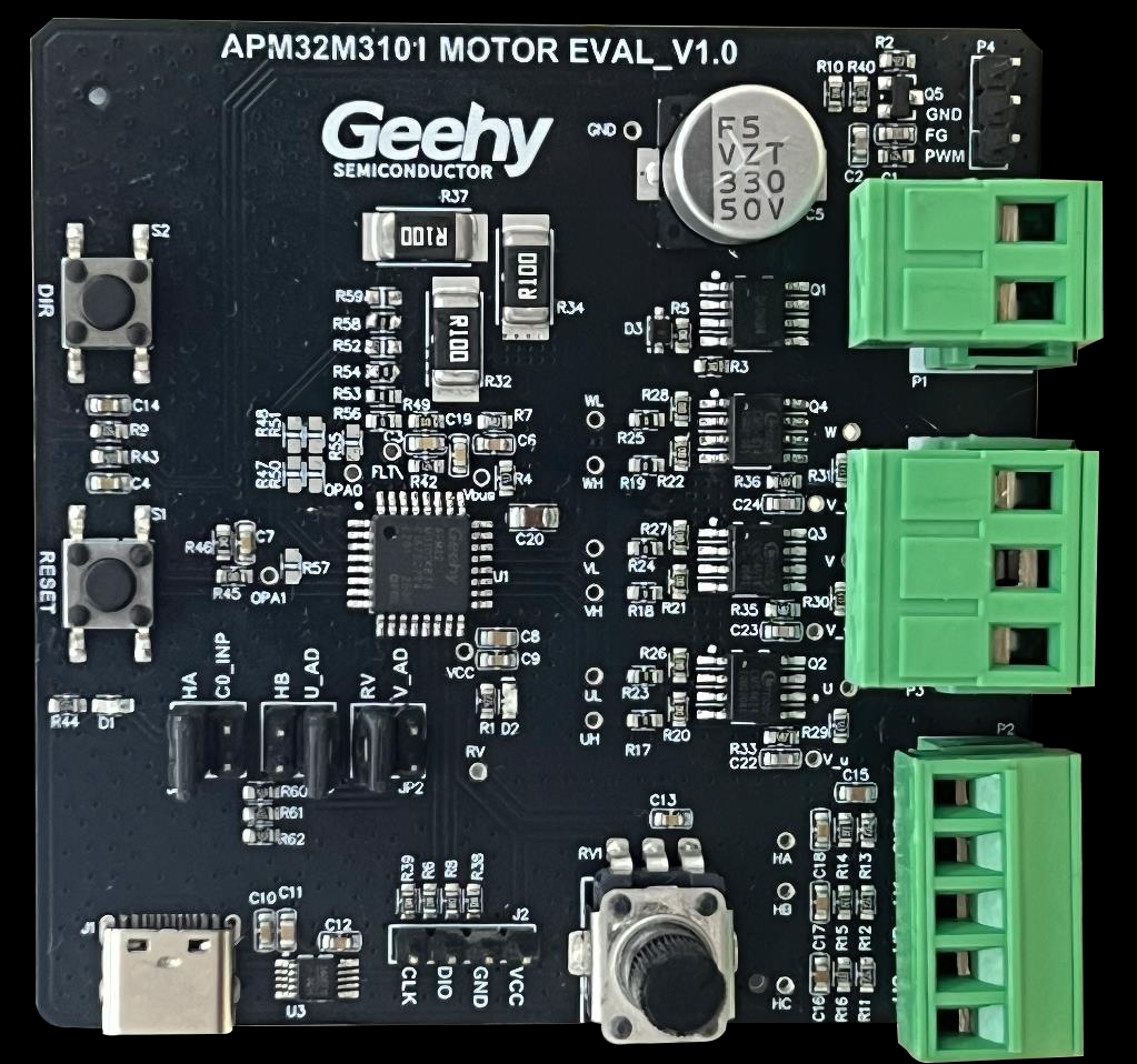
From the G32 product line, G32M3101 is a specialized SoC developed by Geehy specifically for motor control applications, featuring integrated MATH unit, Comparator and OP-AMP.
The latest solution implements a dual-shunt resistor sensorless Field Oriented Control (FOC) scheme based on the G32M3101 architecture.
It is designed to support advanced operational features, including multiple observers with Phase Locked Loop (PLL), flexible open-loop and closed-loop startup modes, and forward/reverse wind startup (flying start).
Furthermore, the solution offers tangible control capabilities such as speed closed-loop and power closed-loop control, ensuring safe operation with a comprehensive suite of protection functions.
The Core Architecture: A Five-Layer Model
A mature motor control project adopts a layered design to achieve high cohesion and low coupling. We categorize the code into: User Layer (USER), Peripheral Driver Layer (BSP_DRV), Motor Control Logic Layer (MOTOR_CONTROL), Algorithm Library Layer (MCLIB), and Chip Support Layer (DDL/CMSIS).
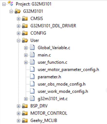
1. User Layer (USER): The System Brain
The User Layer determines the system’s high-level behavior: “When to spin, in what mode, and how to handle errors.”
- Main Entry & Scheduling (
main.c): The starting point of the system. It handles initialization and the Slow Loop task scheduling (e.g., mode switching and non-real-time logic) within the while(1) loop.
- Global Data Skeleton (
Global_Variable.c): Defines the common language of the project, including state machine variables, real-time sampling data, PI parameters, and fault flags.
- Interrupt Entry (
g32m3101_int.c): The trigger point for the Fast Loop. DMA or ADC interrupts usually serve as the high-frequency pulse that executes the FOC control algorithm.
- Configuration Headers:
1) user_motor_parameter_config.h — motor “plant” definition
It defines the physical parameters of the motor (the controlled object), such as electrical/mechanical constants and ratings, serving as the baseline for control and protection scaling.
2) user_obs_mode_config.h — sensing/estimation behavior definition
It defines how rotor angle/speed are estimated (observer mode selection and tuning), including how direction and “windmilling” (forward/reverse) conditions are detected and handled.
3) user_work_mode_config.h — operating strategy definition
It defines which startup and running strategy/path the system follows (mode selection and state-flow choices), determining how the controller transitions through phases like align/startup/spin/closed-loop.
4) parameter.h — global integration and final system knobs (“the master”)
It turns the above choices into executable, system-level constants: hardware reference/scaling, scheduler timing, state-machine thresholds, current ramps, PI/protection thresholds, and fault recovery policies—i.e., the global control and safety “source of truth”.
parameter.h: quick classification of “configuration items”
Group 1) Chip / clock / references (usually kept default)
Includes items like SYS_REFV, SYSCLK_HSE, ADC_REFV.
They set core electrical/time baselines (reference voltages and clock sources) that affect timing and ADC scaling.
Group 2) PWM & scheduling ticks
Includes PWMFREQ / PWM_PERIOD, DEAD_TIME, SLOWLOOP_FREQ.
They define PWM switching characteristics and the control-loop cadence (fast loop vs slow loop).
Group 3) Sampling & scaling baselines (accuracy of current/voltage)
Includes R_SHUNT, CURRENT_OPA_GAIN, I_MAX, UDC_MAX.
They determine how ADC readings convert to real-world units and set the valid measurement/control range.
Group 4) State-machine thresholds & dynamic response (start/stop and responsiveness)
Includes thresholds like STOP_TO_RUN_SPEED, STARTUP_TO_SPIN_SPEED, FREEWHEEL_SPEED, and dynamics like STARTUP_SPD_INC, SPIN_SPD_INC, SPD_DEC, plus timing like FREEWHEEL_TIME, PRECHARGE_TIME.
They govern when states switch and how aggressively speed ramps occur.
Group 5) Current setpoints & transition slopes (torque feel and smoothness)
Includes CUR_ALIGN, CUR_STARTUP, CUR_INC/CUR_DEC, TRANSIT_CUR_INC/TRANSIT_CUR_DEC.
They shape torque production during alignment/start and control how smoothly current commands change across transitions.
Group 6) Protection & fault recovery (fault judgment and restart policy)
This block defines what is considered a fault, how long it must persist to be latched, and whether/how the system is allowed to recover and restart.
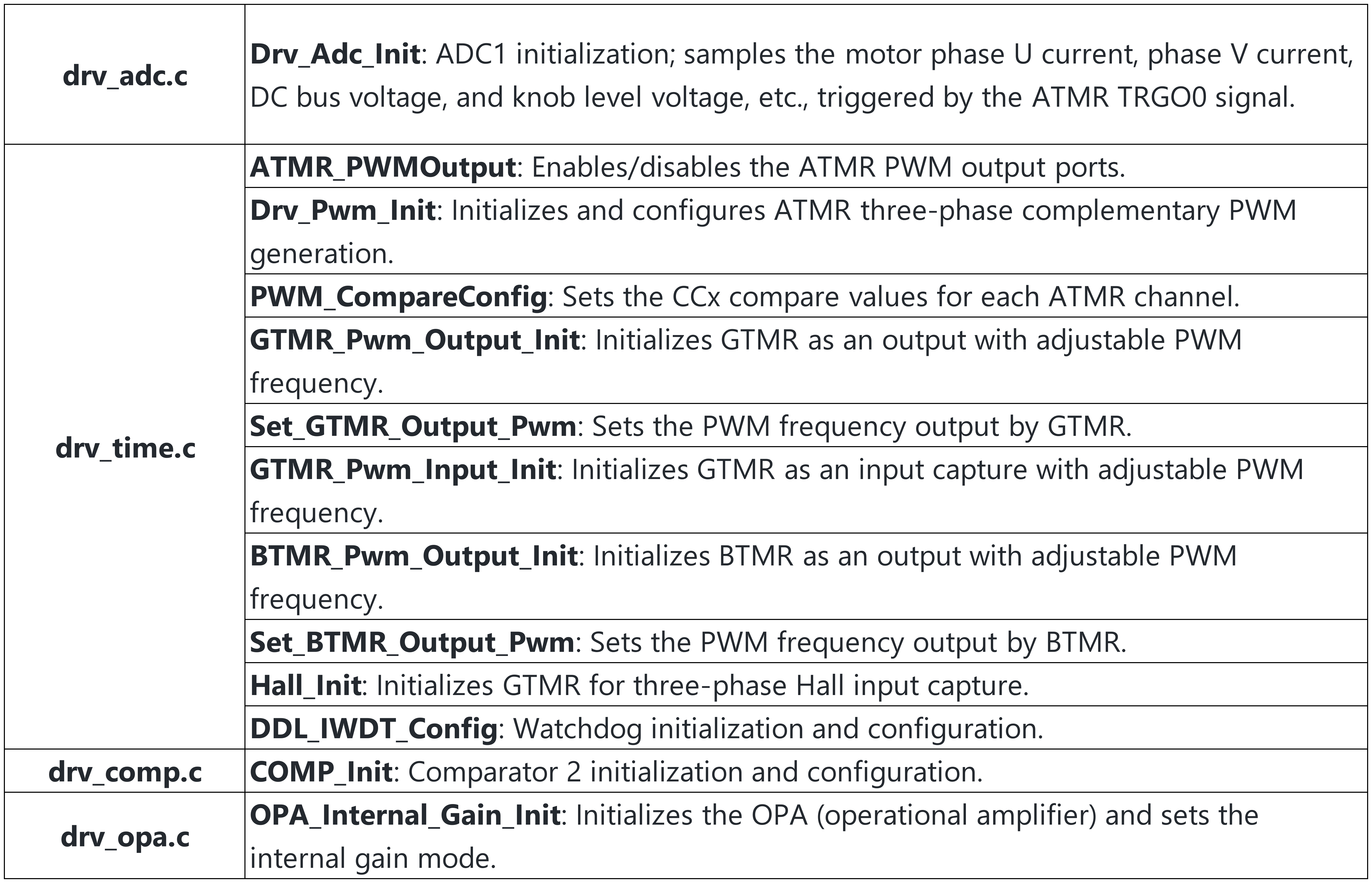
2. Peripheral Driver Layer (BSP_DRV): Senses and Muscles
This layer abstracts register-level operations into stable interfaces, providing reliable I/O channels for the algorithm.
- ADC Sampling Chain (
drv_adc.c): Configures trigger sources (like ATMR TRGO) and channels for phase current, bus voltage, and command voltage (potentiometer).
- PWM & Timers (
drv_timer.c):
- ATMR: Generates 3-phase complementary PWM with dead-time and emergency brake functionality.
- GTMR/BTMR: Used for input capture (measuring external PWM frequency) or auxiliary PWM output for debugging.
- Hardware Protection & Analog Front-End (
drv_comp.c, drv_opa.c): Configures internal comparators for microsecond-level over-current shutdown and OP-Amps for signal conditioning.
3. Motor Control Layer (MOTOR_CONTROL): The Logic Core
This is the heart of the driver, organizing algorithms into a manageable state machine for safe and stable operation.
- Dual-Rate State Machine (
StateMachine.c):
- Fast Loop State Machine: Runs within high-frequency interrupts, tightly bound to FOC current loop execution.
- Slow Loop State Machine: Runs in the main loop, handling commands, delays, and mode transitions.
- FOC Core (
FOC_Ctrl.c):
- Data Processing: ADC offset calibration and scaling.
- Voltage Management: Coordinate transformation (Clarke/Park), circle limitation, and over-modulation.
- Current Loop: Executes the Spin Current PI control to ensure the motor follows the target torque/speed.
- Fault Detection (
fault.c): Real-time monitoring of over-current, over-voltage, stall, and loss-of-step, managing the transition to STOP or FAULT states.
4. Algorithm Library Layer (Geehy_MCLIB): The Mathematical Engine
To maximize efficiency, the core mathematical transforms and observer algorithms are often provided as optimized libraries.
m3101_foc_v12.lib: The “Black Box” containing optimized Clarke/Park transforms, SVPWM, and observer implementations.geehy_lib.c: Acts as a wrapper to interface the library capabilities with the specific project structure.
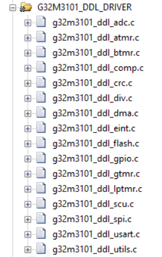
5. Chip Support Layer (CMSIS / DDL): The Foundation
This layer ensures the infrastructure is ready—clock trees, NVIC (interrupt) priorities, and GPIO multiplexing.
To summarize, the G32 Sensorless FOC solution bridges these four critical paths:
- Sampling Loop: PWM trigger → ADC conversion → DMA transfer → Fast Loop interrupt.
- Control Loop: Current sampling → Coordinate transform/PI control → SVPWM → PWM duty cycle update.
- State Loop: Transitioning between INIT, STOP, RUN, and FAULT, including sub-states like Calibration, Alignment, and Startup.
- Protection Loop: A combination of hardware comparators (brake) and software fault detection to ensure the system fails safely.
By understanding this layered architecture, you can move beyond simply “making the motor spin” to building a robust, industrial-grade control system.