Hi everyone,
I am working on a project using the APM32F103CBT6 MCU and implementing Standby (low-power) mode in the firmware. Development is done using Arduino IDE v2.3.2. I want the standby mode to be implemented to reduce the current consumption since my device is battery-operated.
Problem Overview
The firmware flow is as follows:
- On power-up, setup() runs.
- In loop(), if the reset reason is a power-on reset, the device enters Standby mode.
- The MCU wakes up from Standby via an interrupt on PA0 (Wakeup Pin).
- Execution flow and timing are monitored using the Serial Monitor.
With the same firmware and library versions, I am observing different behaviour on two PCBs that:
- Have identical schematics
- Are manufactured by the same vendor
Observed Behavior
- Without Standby mode implemented, both PCBs behave correctly.
- With Standby mode enabled:
- Serial prints before entering Standby appear correctly.
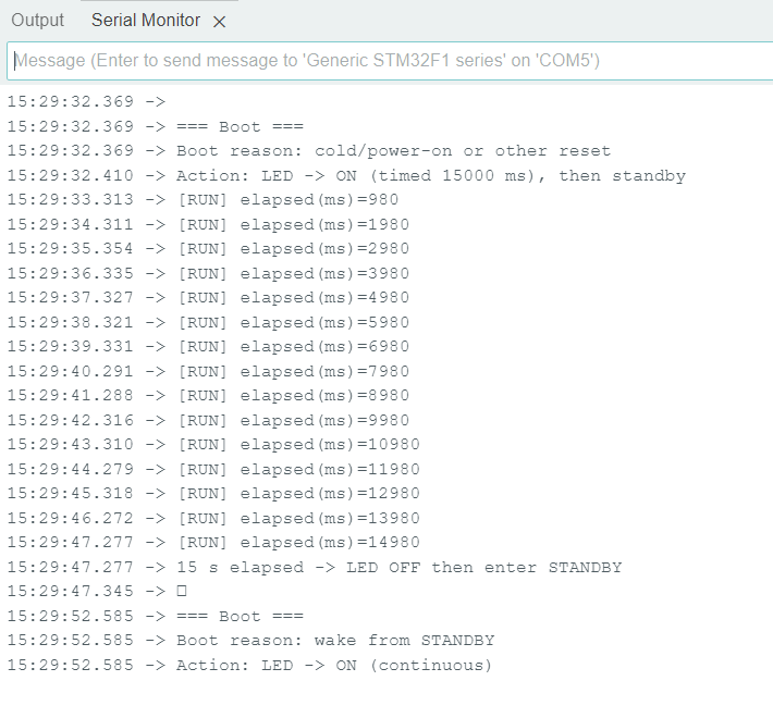
- After waking from Standby:
- One PCB works as expected.
- The other PCB shows:
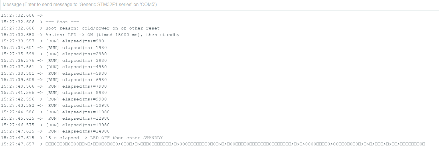
- Garbage characters in the Serial Monitor
- Significantly extended timing
- Example: a programmed delay(30 seconds) takes approximately 1 minute 10 seconds
- All timing sources (delay(), millis(), etc.) appear slowed down
Clock Configuration
- No external crystal or clock source is used.
- The project relies only on the internal clock (HSI).
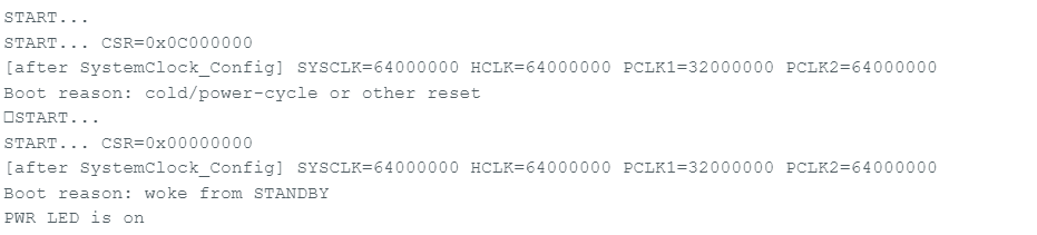
- Clock information (SystemCoreClock, RCC registers) is printed after reset.
- Screenshots are attached for reference
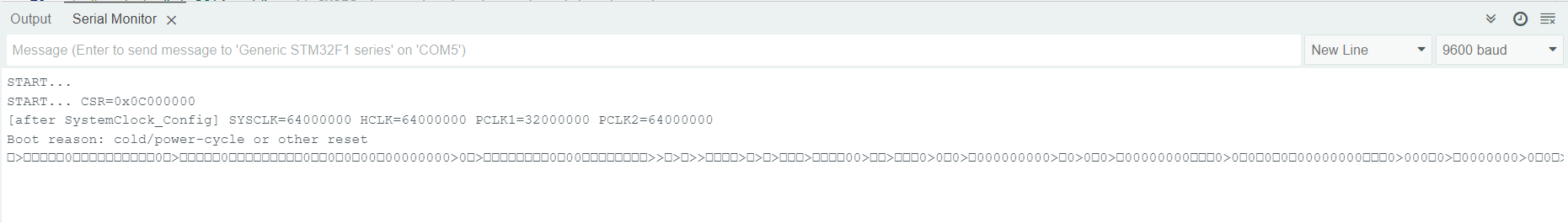
- From the serial output:
- Clocks appear correct after a power-cycle reset
- Clocks appear to be incorrect or degraded after waking from Standby on the problematic PCB
Test Code
I am attaching the test code used to reproduce the issue (shown below for reference):
#include <Arduino.h>
// —————- Pins —————-
#define USB_PWR PB0 // not used in this scenario, keep if needed
#define PWR_LED PB1 // LED output (active HIGH)
// —————- Serial —————-
HardwareSerial Serial1(PA10, PA9); // rx, tx (STM32duino constructor = RX,TX)
#define pc Serial1
// —————- Timing —————-
#define LED_ON_MS 15000UL // 15 seconds
// —————- State —————-
enum State : uint8_t { STATE_15S_ON_THEN_STBY, STATE_LED_ON_FOREVER };
static State state = STATE_15S_ON_THEN_STBY;
static uint32_t t_start = 0;
// —- Helper: Enter Standby (never returns) —-
static void enterStandby()
{
__HAL_RCC_PWR_CLK_ENABLE();
// Make sure LED is off just before entering standby
digitalWrite(PWR_LED, LOW);
// Quiet the UART so we don’t send while clocks change
pc.flush();
delay(2);
pc.end();
delay(5);
// Required RM0008 sequence: disable, clear, then enable wakeup pin
HAL_PWR_DisableWakeUpPin(PWR_WAKEUP_PIN1);
__HAL_PWR_CLEAR_FLAG(PWR_FLAG_WU); // clear any spurious wake
// (Optional) clear StandBy flag so next boot can differentiate cleanly
__HAL_PWR_CLEAR_FLAG(PWR_FLAG_SB);
HAL_PWR_EnableWakeUpPin(PWR_WAKEUP_PIN1); // PA0, rising edge
// Enter Standby (resets on wake)
HAL_PWR_EnterSTANDBYMode();
// Should never get here
while (1) { }
}
// —- Helper: check if we woke from Standby —-
static bool wokeFromStandby()
{
HAL_RCC_PWR_CLK_ENABLE();
return (HAL_PWR_GET_FLAG(PWR_FLAG_SB) != RESET);
}
void setup()
{
// Detect boot reason before changing flags
const bool from_standby = wokeFromStandby();
// Clear flags early so next entry works as expected
__HAL_PWR_CLEAR_FLAG(PWR_FLAG_SB);
__HAL_PWR_CLEAR_FLAG(PWR_FLAG_WU);
// Bring up Serial a moment after reset for stable clocks
delay(10);
pc.begin(9600);
delay(10);
// Optional: confirm clocks
pc.print(“SystemCoreClock=”); pc.println(SystemCoreClock);
uint32_t cr = RCC->CR;
pc.print(“RCC->CR=0x”); pc.println(cr, HEX);
pc.print(“HSIRDY=”); pc.println((cr & RCC_CR_HSIRDY) ? “1”:“0”);
// If you ever use PLL from HSI:
pc.print(“PLLRDY=”); pc.println((cr & RCC_CR_PLLRDY) ? “1”:“0”);
// GPIO
pinMode(PWR_LED, OUTPUT);
digitalWrite(PWR_LED, LOW); // start OFF
pc.println();
pc.println(“=== Boot ===”);
pc.println(from_standby ? “Boot reason: wake from STANDBY” : “Boot reason: cold/power-on or other reset”);
if (from_standby)
{
// Requirement: after waking from standby, keep LED ON continuously
digitalWrite(PWR_LED, HIGH);
state = STATE_LED_ON_FOREVER;
pc.println(“Action: LED -> ON (continuous)”);
}
else
{
// Cold boot: LED ON 15s, then go to standby
digitalWrite(PWR_LED, HIGH);
t_start = millis();
state = STATE_15S_ON_THEN_STBY;
pc.print(“Action: LED -> ON (timed ”);
pc.print(LED_ON_MS);
pc.println(“ ms), then standby”);
}
}
void loop()
{
if (state == STATE_LED_ON_FOREVER)
{
// Nothing else to do; stay awake and keep LED ON
delay(1000);
return;
}
// 15-second timed state then enter standby
if ((millis() - t_start) >= LED_ON_MS)
{
pc.println(“15 s elapsed -> LED OFF then enter STANDBY”);
delay(5);
enterStandby(); // never returns
}
// Optional heartbeat for visibility
static uint32_t lastPrint = 0;
uint32_t now = millis();
if (now - lastPrint >= 1000UL)
{
lastPrint = now;
pc.print(“[RUN] elapsed(ms)=”);
pc.println(now - t_start);
}
}
Test Results
Attached the screenshots for your reference.
Case 1 – Problematic PCB
- Serial output contains garbage after Standby wake-up
- All timing functions run slower than expected
Case 2 – Proper PCB
- Serial output and timing behave correctly
I have also included schematic diagrams for the power and controller circuits
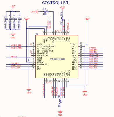
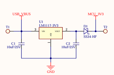
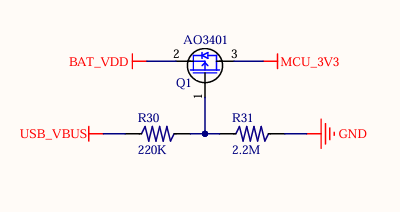
Question
Why would two PCBs with the same schematic and firmware exhibit different clock behavior after exiting Standby mode, leading to timing issues on one board?
What could cause the system clock to collapse or run slower after Standby on only one PCB, and how can this be fixed?
Please let me know if additional information, measurements, or logs are required from my side.
Thanks in advance for your help.