1. Introduction
I recently received the APM32F411 TINY board from Geehy. This newly launched product boasts the following features:
Arm® Cortex®-M4F core operating at 120MHz for high computational capability.
Various operating modes and rich high-precision peripherals and communication interfaces.
Built-in CRC32 computation unit for a highly integrated and reliable SoC solution.
A cost-effective expansion product in the APM32F4 MCU series, effectively meeting balanced requirements for power consumption, performance, and cost-effectiveness.
Suitable for applications such as power, instrumentation, industrial control, home appliances, IoT, new energy, smart buildings, and more.
For more details, visit their official website: https://geehy.com/apm32?id=81
Now, let’s delve into the APM32F411 TINY board.
2. APM32F411 TINY Board

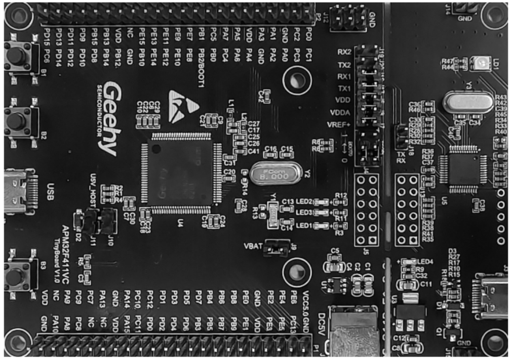
The board is divided into two parts: the right side features the onboard debugger, and the left side hosts the APM32F411 MCU. External resources include 1 Type-C (USB FS), 2 keys, 2 LEDs, and 2 USART (connected to the onboard debugger).
3. Connecting the Onboard Debugger to the Computer
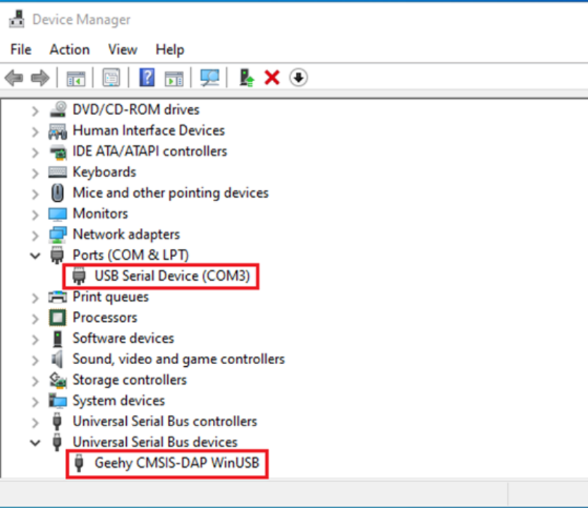
Connect the Type-C cable to the onboard debugger, and you’ll see an additional serial port and a “Geehy CMSIS-DAP WinUSB” device in the device manager.

This indicates that they use a WinUSB-based CMSIS-DAP firmware for the onboard debugger, supporting serial data transmission.
4. Onboard USART and LED Demo Coding
With the onboard debugger, why not blink an LED and print something through the serial port? (#^.^#).
Download the SDK from their official website: https://geehy.com/uploads/tool/APM32F4xx_SDK_V1.4.zip
To evaluate LED and USART functionality, I’ll choose USART1 for verification with the following steps:
①Initialize USART1.
②Write USART1 receive interrupt and check for carriage return to trigger transmission.
For convenience, I directly modified the provided “SysTick_TimeBase” from the official SDK (which includes LED operations, no need to thank me).
USART Initialization:
void USART1_Init(void)
{
GPIO_Config_T GPIO_configStruct;
USART_Config_T usartConfigStruct;
GPIO_ConfigStructInit(&GPIO_configStruct);
/* Enable GPIO clock */
RCM_EnableAHB1PeriphClock(RCM_AHB1_PERIPH_GPIOA);
RCM_EnableAPB2PeriphClock(RCM_APB2_PERIPH_USART1);
/* Connect PXx to USARTx_Tx */
GPIO_ConfigPinAF(GPIOA, GPIO_PIN_SOURCE_9, GPIO_AF_USART1);
/* Connect PXx to USARTx_Rx */
GPIO_ConfigPinAF(GPIOA, GPIO_PIN_SOURCE_10, GPIO_AF_USART1);
/* Configure USART Tx as alternate function push-pull */
GPIO_configStruct.mode = GPIO_MODE_AF;
GPIO_configStruct.pin = GPIO_PIN_9;
GPIO_configStruct.speed = GPIO_SPEED_50MHz;
GPIO_Config(GPIOA, &GPIO_configStruct);
/* Configure USART Rx as input floating */
GPIO_configStruct.mode = GPIO_MODE_AF;
GPIO_configStruct.pin = GPIO_PIN_10;
GPIO_Config(GPIOA, &GPIO_configStruct);
/* USART configuration */
usartConfigStruct.baudRate = 115200;
usartConfigStruct.hardwareFlow = USART_HARDWARE_FLOW_NONE;
usartConfigStruct.mode = USART_MODE_TX_RX;
usartConfigStruct.parity = USART_PARITY_NONE;
usartConfigStruct.stopBits = USART_STOP_BIT_1;
usartConfigStruct.wordLength = USART_WORD_LEN_8B;
USART_Config(USART1, &usartConfigStruct);
USART_EnableInterrupt(USART1,USART_INT_RXBNE);
NVIC_EnableIRQRequest(USART1_IRQn,1,0);
/* Enable USART */
USART_Enable(USART1);
}
USART interrupt service function:
void USART1_Isr(void)
{
/* USART1 Recieve Data */
if(USART_ReadStatusFlag(USART1, USART_FLAG_RXBNE) == SET)
{
txrxDataBufUSART1[rxCountUSART1] = (uint8_t)USART_RxData(USART1);
rxCountUSART1++;
if((txrxDataBufUSART1[rxCountUSART1-1] == 0x0A)&&(txrxDataBufUSART1[rxCountUSART1-2] == 0x0D))
{
for(txCountUSART1 = 0;txCountUSART1 < rxCountUSART1;txCountUSART1++)
{
USART_TxData(USART1,txrxDataBufUSART1[txCountUSART1]);
/* wait for the data to be send */
while (USART_ReadStatusFlag(DEBUG_USART, USART_FLAG_TXBE) == RESET);
}
rxCountUSART1 = 0;
}
}
}
Main function:
int main(void)
{
USART1_Init();
APM_LEDInit(LED2);
APM_LEDInit(LED3);
printf("APM32F411 TINY Demo\r\n");
/* SysTick Initialization */
SysTick_Init();
while (1)
{
APM_LEDToggle(LED2);
/* Precise Delay 1ms */
SysTick_Delay_ms(1000);
APM_LEDToggle(LED3);
}
}
5. Demo Download
In the magic wand, select simulation download settings, and choose CMSIS-DAP Debugger.

Further settings:

Then compile the program and proceed with the download.
6. Results
After downloading the program to the board, the onboard LED2/3 alternately blinks. If the serial assistant is already open, it will print “APM32F411 TINY Demo.” Use the serial assistant to send data (remember to check “Send New Line (Line by Line)”), and it will reply with the same data.
