madhu
/* Resets the clock configuration /
RCM_Reset();
/ Set if necessary /
//RCM_SetHSITrim(8);
RCM_EnableHSI(); // HSI freq: 8MHz
/ Directly set to SYSCLK = 8MHz /
RCM_ConfigSYSCLK(RCM_SYSCLK_SEL_HSI);
/ Set HCLK (includes GPIO & DMA) /
/ To ensure real-time data transmission,GPIO clock frequency cannot be divided /
/ HCLK = SYSCLK / 2 = 4MHz/
RCM_ConfigAHB(RCM_SYSCLK_DIV_2);
/ Set APBCLK (ADC) /
/ APBCLK = HCLK / 1 = 4MHz */
RCM_ConfigAPB(RCM_HCLK_DIV_1);
/* Set when initialize ADC sequance /
/ ADCCLK = APBCLK / 2 = 2MHz */
ADC_ClockMode(ADC_CLOCK_MODE_SYNCLKDIV2);
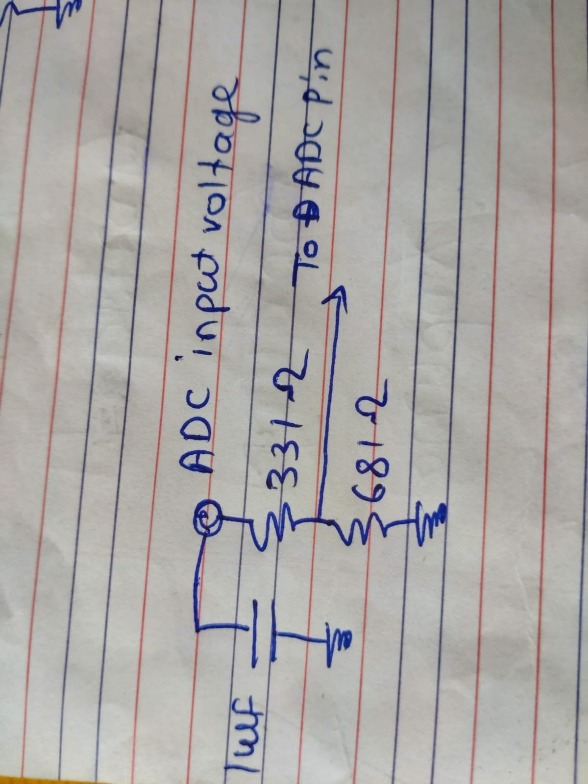
[unknown] Please provide more information. Does your ADC signal input section have a filtering capacitor?
[unknown] Please provide more information. Does your ADC signal input section have a filtering capacitor?
[unknown] Please provide more information. Does your ADC signal input section have a filtering capacitor?