In our [previous post], we explored the multi-layered architecture of the G32M3101 motor driver project. Understanding the “where” and “why” of the file structure is essential, but now it is time for the “how.”
This guide outlines the systematic workflow to move from a raw motor to a stable, high-performance closed-loop system. We have condensed this into 11 actionable steps to help you navigate the debugging process efficiently.
1. Parameter Pre-configuration (Matching the Motor)
Before powering up, you must define the electrical “DNA” of your motor.
- Measure Motor Parameters: Use an LCR bridge or multimeter to obtain Phase Resistance ($R_s$), Phase Inductance ($L_s$), Magnetic Flux, Pole Pairs, and Rated Speed/Power.
- Input Configuration: Fill in these core electrical parameters in
user_motor_parameter_config.h.
- Critical Notes:
- Select appropriate three-phase sampling resistors based on the rated current to ensure measurement range and precision.
- Configure Current Base (I_MAX) and Voltage Base (UDC_MAX) in
parameter.h according to your board’s hardware scaling.
- For closed-loop performance, distinguish between Lq and Ld if the motor is salient.
2. Hardware Verification (Ensuring Reliability)
- Voltage Stability: Verify the Bus Voltage is stable and that the Op-amp bias voltage sits at approximately 2.5V ±0.05V.
- Hardware Over-current Protection: This is your safety net. Simulate an over-current input to verify that the system triggers the ATMR Hardware Over-current Protection Interrupt. Ensure the hardware brake/shutdown link is functional before spinning the motor.
3. Motion State Parameters (Thresholds & Ramps)
Define the boundaries for the state machine:
- Speed Thresholds: Set the transition points for
STOP → RUN, STARTUP → SPIN, and RUN → FREEWHEEL.
- Acceleration/Deceleration: Ensure these values are within the mechanical capabilities of the motor and its load.
- Current Settings: Define the Alignment Current, Open-loop Startup Current, and the Current Slew Rate (A/s).
4. Simplify Early Detection
For the initial spin, disable advanced protections (such as stall detection or complex EMF-based checks). Once the motor spins stably, re-enable these features one by one and fine-tune their thresholds and filter times.
5. PI Controller Tuning (Current First, Speed Later)
- Core Loops: Tune the Current Loop PI (Id/Iq) first, followed by the Speed Loop PI.
- Tuning Principle: For the current loop, increase Kp gradually until the response is fast but stable, then introduce/increase Ki to eliminate steady-state error.
6. Initial Run Strategy: Open-loop to Closed-loop
The safest way to start is the “Open-loop to Closed-loop” transition:
- Configure
user_work_mode_config.h to Open-loop transition mode.
- Initial Recommendation: Disable “Flying Start” (Windmill detection) and “IPD” (Initial Position Detection) for the first few runs.
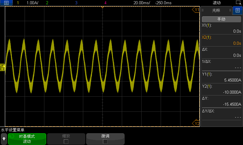
7. Run-Align Stage: Stabilizing the Current Loop
This is the most critical first hurdle. Lock the state machine in the Run-Align state within StateMachine.c:
- Fix the rotor angle at 0°.
- Apply a fixed Q-axis current (start small and increase).
- Goal: Tune the DQ Current Loop PI here. Observe the Vq and Iq waveforms; they must be stable before proceeding.
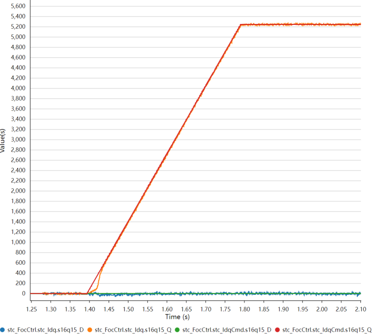
8. Run-Startup: Matching Current with Acceleration
During the open-loop acceleration phase:
- Apply a fixed Q-axis current and accelerate based on a defined ramp.
- The Key: The Q-axis current must match the acceleration slope. If the current is too low for the ramp, the motor will lose sync.
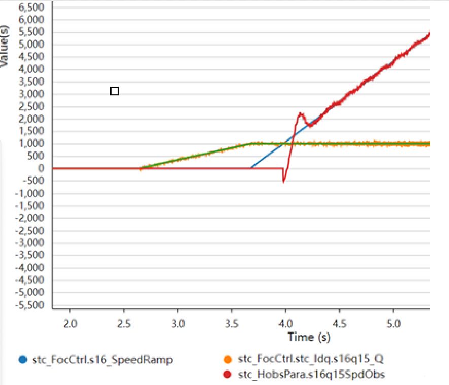
- Observer Convergence: Monitor the high-speed observer and its PLL PI parameters. Compare:
stc_FocCtrl.s16_SpeedRamp (Target ramp speed)stc_HobsPara.s16q15SpdObs (Observed speed)
- Target: The observed speed should closely follow the ramp speed.
9. The Switch: Speed Thresholds & Speed PI
- Transition: The transition from open to closed loop depends on whether the observer has converged and the speed has reached the threshold.
- Threshold Tip: Start with a minimum closed-loop speed of about 15% of the rated speed.
- Speed Loop PI: Adjust based on the load’s inertia and damping. Increase Kp until the system responds well without oscillating.
10. Fault Diagnostics
If the system trips, use the M1FaultID_Record variable to identify the fault code. This allows you to pinpoint whether the issue lies in thresholds, filtering, sampling bias, observer convergence, or hardware false triggers.
11. Advanced: Direct Closed-loop Startup
Once the transition mode is stable, you can attempt direct closed-loop startup:
- Set
user_work_mode_config.h to Closed-loop Startup Mode.
- In
user_obs_mode_config.h, select your Low-speed Observer type.
- Choose between Direct Speed Closed-loop or Current Ramp transition to Speed Loop.
- Tuning Strategy: If the low-speed observer fails to see rotation, increase gain/PLL gain. If the motor jitters, the gain is likely too high.
Next Steps: By following this sequence, you transform a complex FOC system into a series of manageable debugging steps. If you need the demo kit from Geehy, please leave a comment here or contact: https://global.geehy.com/about/contact